Shared Projects by dewhisna
Shared Projects by dewhisna
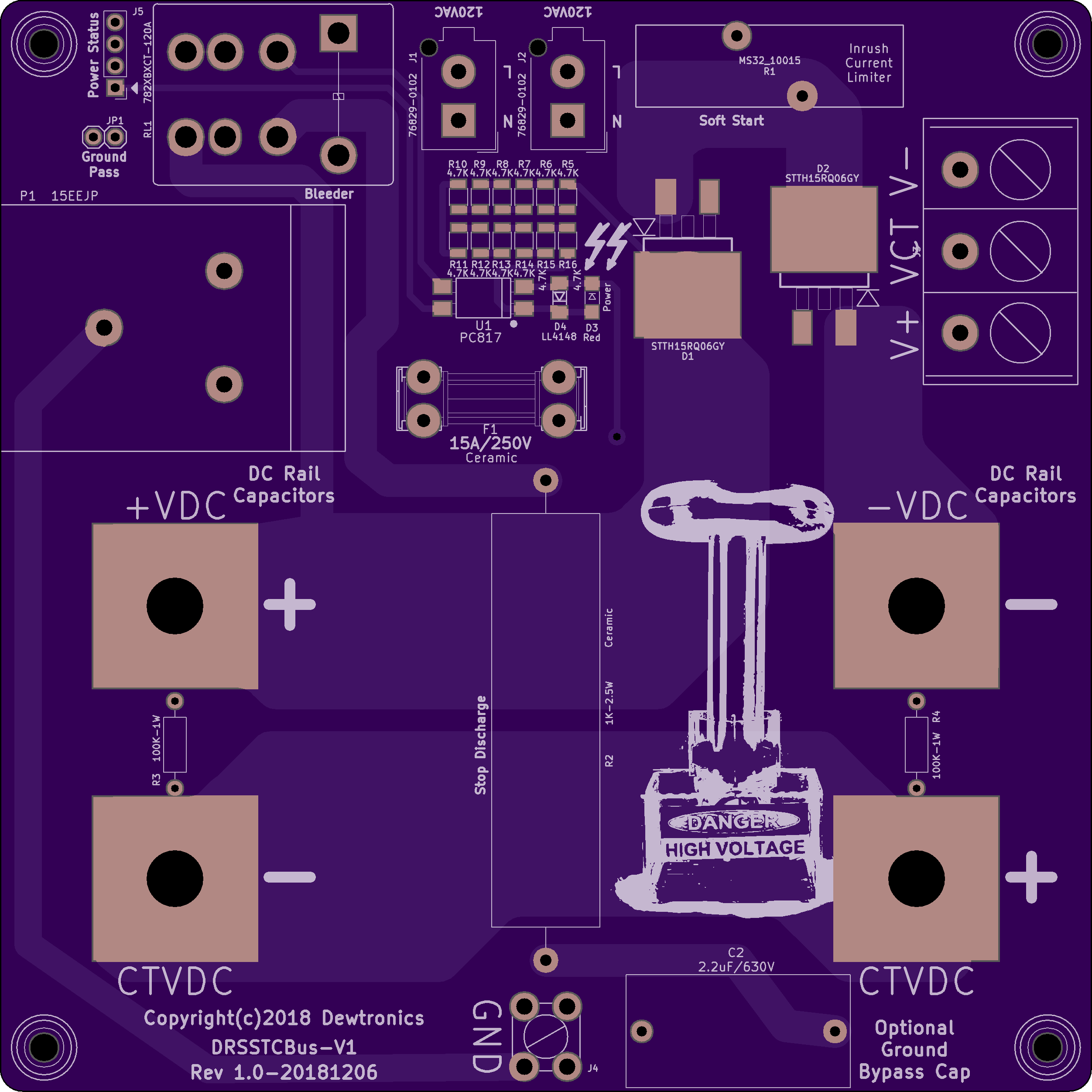
DRSSTC Bus Supply V1

2 layer board of 5.01 x 5.01 inches (127.2 x 127.2 mm)
Uploaded:
December 24, 2018
Shared:
March 01, 2019
Total Price:
$125.30
Dual-Resonance Solid-State Tesla Coil 340VDC Bus Supply (from 120VAC only).
NOTE: This board has been replaced by the newer DRSSTC Bus Supply V2 design!
This version is designed to be used with large electrolytic capacitors, such as Cornel…
Dual-Resonance Solid-State Tesla Coil 340VDC Bus Supply (from 120VAC only).
NOTE: This board has been replaced by the newer DRSSTC Bus Supply V2 design!
This version is designed to be used with large electrolytic capacitors, such as Cornell-Dubilier 500C series screw-terminal mount. The prototype circuit is using two 10,000uF 450VDC Cornell-Dubilier 500C capacitors. Or optionally, you can use the DRSSTC Bus Caps V2 board to mount smaller, through-hole, bus caps to this board using 710-7461097 : Würth Terminals WP-BUFU Pin-Plate 16Pin Bush M6 180A.
ERRATA: LED D3 and Opto-Isolator U1 cannot both be populated or else only one of the two will function, based on their required voltage drop. Both are designed as “HV Power On” indicators, only one is on-board and the other is remote. Decide if you want your indicator on-board or remote and populate accordingly. OR, you can modify the circuit so that D3 and U1 are in series instead of parallel. For that, cut the two traces leading from D4 to D3, and place a jumper between the anode of D4 (the LL4148) and the cathode of D3 (the visible LED). That will place the LED internal to the U1 Opto-Isolator in series with the visible LED D3 and allow both to function correctly (this is the preferred fix).
This board, along with the DRSSTC Bridge V2 replace the original DRSSTC Bridge V1.
Show full description
Dual-Resonance Solid-State Tesla Coil 340VDC Bus Supply (from 120VAC only).
NOTE: This board has been replaced by the newer DRSSTC Bus Supply V2 design!
This version is designed to be used with large electrolytic capacitors, such as Cornel…
Dual-Resonance Solid-State Tesla Coil 340VDC Bus Supply (from 120VAC only).
NOTE: This board has been replaced by the newer DRSSTC Bus Supply V2 design!
This version is designed to be used with large electrolytic capacitors, such as Cornell-Dubilier 500C series screw-terminal mount. The prototype circuit is using two 10,000uF 450VDC Cornell-Dubilier 500C capacitors. Or optionally, you can use the DRSSTC Bus Caps V2 board to mount smaller, through-hole, bus caps to this board using 710-7461097 : Würth Terminals WP-BUFU Pin-Plate 16Pin Bush M6 180A.
ERRATA: LED D3 and Opto-Isolator U1 cannot both be populated or else only one of the two will function, based on their required voltage drop. Both are designed as “HV Power On” indicators, only one is on-board and the other is remote. Decide if you want your indicator on-board or remote and populate accordingly. OR, you can modify the circuit so that D3 and U1 are in series instead of parallel. For that, cut the two traces leading from D4 to D3, and place a jumper between the anode of D4 (the LL4148) and the cathode of D3 (the visible LED). That will place the LED internal to the U1 Opto-Isolator in series with the visible LED D3 and allow both to function correctly (this is the preferred fix).
This board, along with the DRSSTC Bridge V2 replace the original DRSSTC Bridge V1.
Show full description
-
Actions
- Order Board
- Download
- Permalink
- Embed link
Ordering shared project
Hey there! Before ordering, make sure you have all the info you need to complete and use this design. This usually means a component list, and sometimes additional information such as assembly notes, source code, or usage guides.Since this is a project designed by a community member, it may contain design errors that prevent it from working as intended. OSH Park cannot place any guarantees about the functionality or correctness of the design.
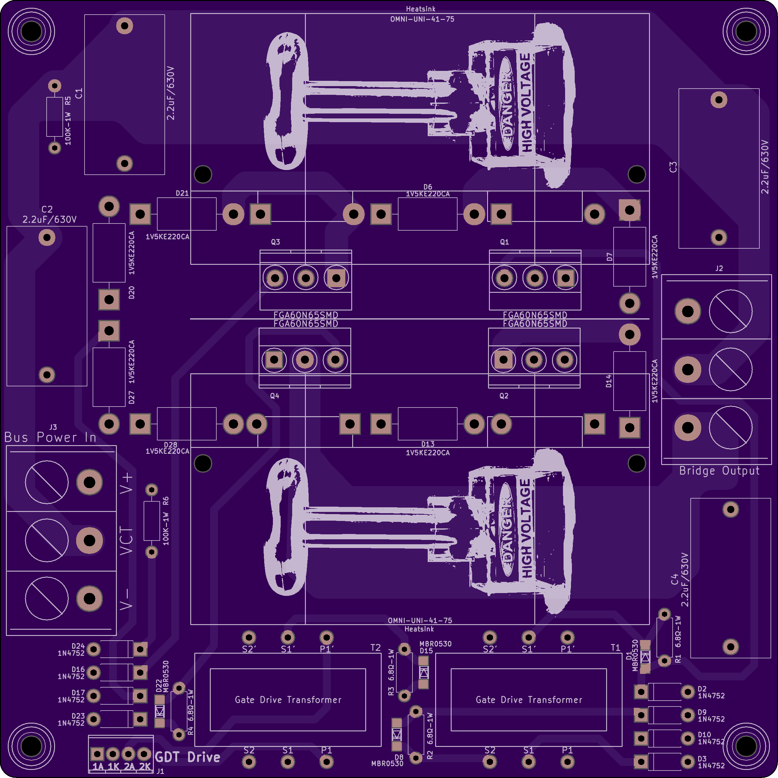
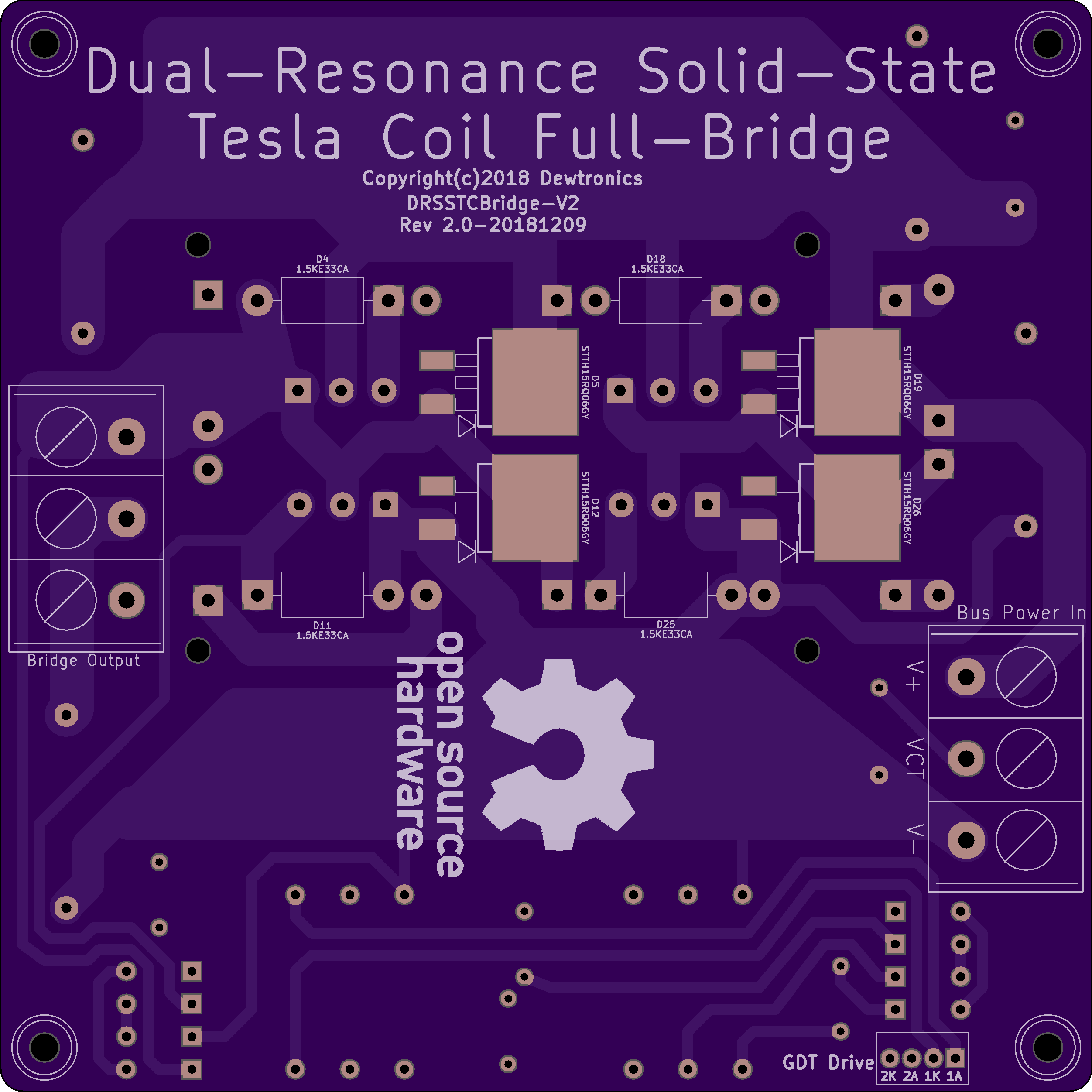
DRSSTC Bridge V2
2 layer board of 5.01 x 5.01 inches (127.2 x 127.2 mm)
Uploaded:
December 24, 2018
Shared:
March 01, 2019
Total Price:
$125.30
Dual Resonance Solid-State Tesla Coil Full-Bridge V2.
Dual Resonance Solid-State Tesla Coil Full-Bridge V2.
Dual Resonance Solid-State Tesla Coil Full-Bridge V2.
Dual Resonance Solid-State Tesla Coil Full-Bridge V2.
-
Actions
- Order Board
- Download
- Permalink
- Embed link
Ordering shared project
Hey there! Before ordering, make sure you have all the info you need to complete and use this design. This usually means a component list, and sometimes additional information such as assembly notes, source code, or usage guides.Since this is a project designed by a community member, it may contain design errors that prevent it from working as intended. OSH Park cannot place any guarantees about the functionality or correctness of the design.
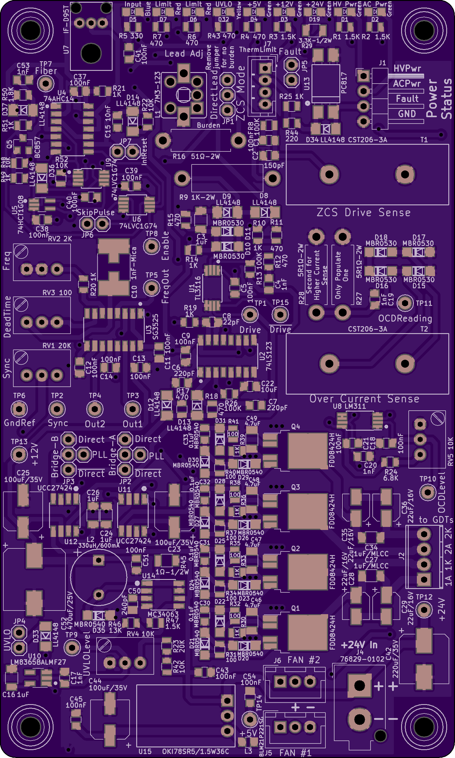
Dual Resonance Solid-State Tesla Coil Driver V2

2 layer board of 3.01 x 5.01 inches (76.4 x 127.2 mm)
Uploaded:
December 24, 2018
Shared:
March 01, 2019
Total Price:
$75.20
Do NOT Build This Board It has been replaced by the DRSSTC Driver V2.1.
Driver board for a Dual-Resonance Solid-State Musical Tesla Coil. This version replaces the older V1 version. This de…
Do NOT Build This Board It has been replaced by the DRSSTC Driver V2.1.
Driver board for a Dual-Resonance Solid-State Musical Tesla Coil. This version replaces the older V1 version. This design features a zero-current-switching phase-lead circuit, an over-current detection/lockout circuit, an under-voltage lockout circuit, and a PLL-based adjustable dead-time delay. Requires regulated 24VDC power supply. And is designed to be used with either the original DRSSTC Full Bridge Board or the DRSSTC V2 Bridge Board with the DRSSTC Bus Supply V1.
This board adds an interface for a thermal (or other) shutdown (See the DRSSTC Thermal Limiter Board V1 ). It also replaces the UCC37322 driver chips, which kept frying on the V1 board, with UCC27424 driven FDD8424H push-pull MOSFET pairs for driving the gate-drive transformers, allowing for much higher current gate drive. And, this board also supports “skip pulse” (or specifically “skip IGBT drive cycle”) mode in addition to the “skip interrupter” mode typically used. This allows harder driving to the over-current detector threshold.
ERRATA:
1) Resistor R45, which is the current-limiter setting for the on-board +12volt switching power supply, should be 0.2-ohm 1/2W instead of 1-ohm 1/2W. That will allow a full 750mA output from the +12v supply instead of being limited to 150mA, which wasn’t even enough to drive the cooling fan (which needs around 370mA).
2) Similarly, diode D35, in that switching supply circuit, should not be a MBR0540, which is only rated for 500mA. Instead, it should be at least a 1A part, or preferably a PMEG3020ER,115 Schottky diode, which is rated at 2A and has a very low Vf of 365mV for improved efficiency, and is a drop-in replacement for the originally spec’d part.
3) There is a logic error in the lockout circuit that causes a race-condition with the U9 flip-flop (74LVC1G74) between the fiber-optic edge detect signal on the set-input and the main fiber-optic signal on the clock pin. This can cause the system to never start and results in only a short burst of output at the beginning of each interrupter pulse, and it also prevents the skip-pulse mode from working at all.
To resolve, the fiber optic input signal needs to be removed from pin 1 of U9. And the skip-pulse signal on pin 2 needs to move to pin 1. And pin 2 needs to get tied to +5v. To do this, cut the trace leading into pin 1 of U9 (leaving the 90-degree junction intact where it runs under U4), and cut the trace leading into pin 2 of U9 between U9 and resistor R52. Solder a jumper between pin 1 of U9 and R52, on the end where the trace to pin 2 was cut (this takes care of moving the skip-pulse signal from pin 2 to pin 1). And solder a small jumper wire to pin 2 of U9 that runs to +5v. The closest and probably most convenient point for +5v is the far end of capacitor C40, which is the power decoupling capacitor for U9. This jumper can be quite tricky as it has to solder to a single pin on a TSSOP package (0.65mm pin-spacing).
4) Do NOT enable the PLL mode unless you swap U11 and U12 from the non-inverting UCC27424 to the inverting UCC27423 part. Since the FDD8424H output driver transistors invert the output from these chips, if the SG3525 is used with the non-inverting UCC27424, then the dead-time from SG3525 will be converted into intentional overlap between the high-side and low-side of the bridge and you’ll blow the bridge off the board faster than you can blink!! Another alternative might be to use the SG3527 for U3 instead of the SG3525, but it might be difficult to locate since the SG3527 is obsolete.
5) Since the high-side of the FDD8424H circuit is only a momentarily triggered (AC Coupled) state, the disabled state for U11 and U12 need to be high to keep the low-side of the FDD8424H parts activated. However, the enable pin on the UCC27424 sets the outputs low when disabling the output. This will cause a momentary trigger of the FDD8424H to high and then go high impedance when disabling the output. This means the gates of the bridge will be left in a floating state and can possibly turn on unintentionally. The fix for this is to not use the enable inputs of U11 and U12 (pins 1 and 8) at all and instead tie them high (or use UCC27323 parts instead which have no enable signal). Then, add ‘AND’ gates to ‘AND’ the enable output pin 5 of U6 (74LVC1G74) with the ‘Direct’ and ‘~Direct’ outputs of U1 (TL3116 pins 7 and 8) to make the input signals to U11 and U12, via JP2 and JP3, instead of just using ‘Direct’ and ‘~Direct’ only. And switch to the inverting UCC27423 (or UCC27323), which also fixes Errata Item #4. This one is pretty much a showstopper for this board, as it would require extensive surgery to fix. Therefore, it’s recommended that you Do Not Build This Board .
This errata has been resolved in DRSSTC Driver V2.1.
Show full description
Do NOT Build This Board It has been replaced by the DRSSTC Driver V2.1.
Driver board for a Dual-Resonance Solid-State Musical Tesla Coil. This version replaces the older V1 version. This de…
Do NOT Build This Board It has been replaced by the DRSSTC Driver V2.1.
Driver board for a Dual-Resonance Solid-State Musical Tesla Coil. This version replaces the older V1 version. This design features a zero-current-switching phase-lead circuit, an over-current detection/lockout circuit, an under-voltage lockout circuit, and a PLL-based adjustable dead-time delay. Requires regulated 24VDC power supply. And is designed to be used with either the original DRSSTC Full Bridge Board or the DRSSTC V2 Bridge Board with the DRSSTC Bus Supply V1.
This board adds an interface for a thermal (or other) shutdown (See the DRSSTC Thermal Limiter Board V1 ). It also replaces the UCC37322 driver chips, which kept frying on the V1 board, with UCC27424 driven FDD8424H push-pull MOSFET pairs for driving the gate-drive transformers, allowing for much higher current gate drive. And, this board also supports “skip pulse” (or specifically “skip IGBT drive cycle”) mode in addition to the “skip interrupter” mode typically used. This allows harder driving to the over-current detector threshold.
ERRATA:
1) Resistor R45, which is the current-limiter setting for the on-board +12volt switching power supply, should be 0.2-ohm 1/2W instead of 1-ohm 1/2W. That will allow a full 750mA output from the +12v supply instead of being limited to 150mA, which wasn’t even enough to drive the cooling fan (which needs around 370mA).
2) Similarly, diode D35, in that switching supply circuit, should not be a MBR0540, which is only rated for 500mA. Instead, it should be at least a 1A part, or preferably a PMEG3020ER,115 Schottky diode, which is rated at 2A and has a very low Vf of 365mV for improved efficiency, and is a drop-in replacement for the originally spec’d part.
3) There is a logic error in the lockout circuit that causes a race-condition with the U9 flip-flop (74LVC1G74) between the fiber-optic edge detect signal on the set-input and the main fiber-optic signal on the clock pin. This can cause the system to never start and results in only a short burst of output at the beginning of each interrupter pulse, and it also prevents the skip-pulse mode from working at all.
To resolve, the fiber optic input signal needs to be removed from pin 1 of U9. And the skip-pulse signal on pin 2 needs to move to pin 1. And pin 2 needs to get tied to +5v. To do this, cut the trace leading into pin 1 of U9 (leaving the 90-degree junction intact where it runs under U4), and cut the trace leading into pin 2 of U9 between U9 and resistor R52. Solder a jumper between pin 1 of U9 and R52, on the end where the trace to pin 2 was cut (this takes care of moving the skip-pulse signal from pin 2 to pin 1). And solder a small jumper wire to pin 2 of U9 that runs to +5v. The closest and probably most convenient point for +5v is the far end of capacitor C40, which is the power decoupling capacitor for U9. This jumper can be quite tricky as it has to solder to a single pin on a TSSOP package (0.65mm pin-spacing).
4) Do NOT enable the PLL mode unless you swap U11 and U12 from the non-inverting UCC27424 to the inverting UCC27423 part. Since the FDD8424H output driver transistors invert the output from these chips, if the SG3525 is used with the non-inverting UCC27424, then the dead-time from SG3525 will be converted into intentional overlap between the high-side and low-side of the bridge and you’ll blow the bridge off the board faster than you can blink!! Another alternative might be to use the SG3527 for U3 instead of the SG3525, but it might be difficult to locate since the SG3527 is obsolete.
5) Since the high-side of the FDD8424H circuit is only a momentarily triggered (AC Coupled) state, the disabled state for U11 and U12 need to be high to keep the low-side of the FDD8424H parts activated. However, the enable pin on the UCC27424 sets the outputs low when disabling the output. This will cause a momentary trigger of the FDD8424H to high and then go high impedance when disabling the output. This means the gates of the bridge will be left in a floating state and can possibly turn on unintentionally. The fix for this is to not use the enable inputs of U11 and U12 (pins 1 and 8) at all and instead tie them high (or use UCC27323 parts instead which have no enable signal). Then, add ‘AND’ gates to ‘AND’ the enable output pin 5 of U6 (74LVC1G74) with the ‘Direct’ and ‘~Direct’ outputs of U1 (TL3116 pins 7 and 8) to make the input signals to U11 and U12, via JP2 and JP3, instead of just using ‘Direct’ and ‘~Direct’ only. And switch to the inverting UCC27423 (or UCC27323), which also fixes Errata Item #4. This one is pretty much a showstopper for this board, as it would require extensive surgery to fix. Therefore, it’s recommended that you Do Not Build This Board .
This errata has been resolved in DRSSTC Driver V2.1.
Show full description
-
Actions
- Order Board
- Download
- Permalink
- Embed link
Ordering shared project
Hey there! Before ordering, make sure you have all the info you need to complete and use this design. This usually means a component list, and sometimes additional information such as assembly notes, source code, or usage guides.Since this is a project designed by a community member, it may contain design errors that prevent it from working as intended. OSH Park cannot place any guarantees about the functionality or correctness of the design.
Dual-Resonance Solid-State Tesla Coil MIDI Interrupter Dual 328PB V1
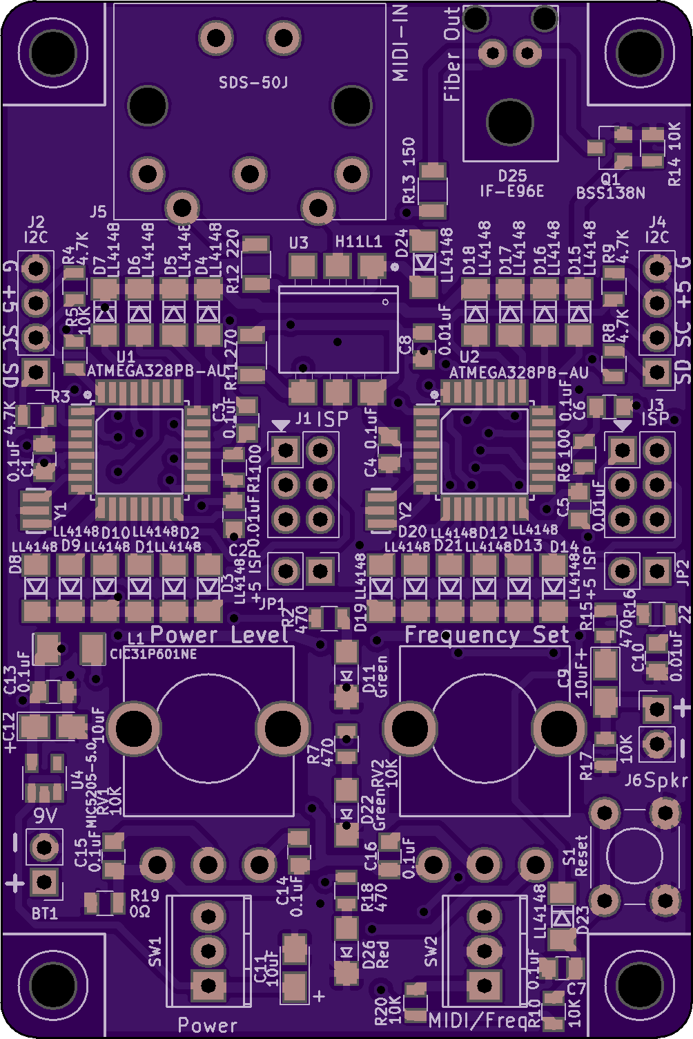
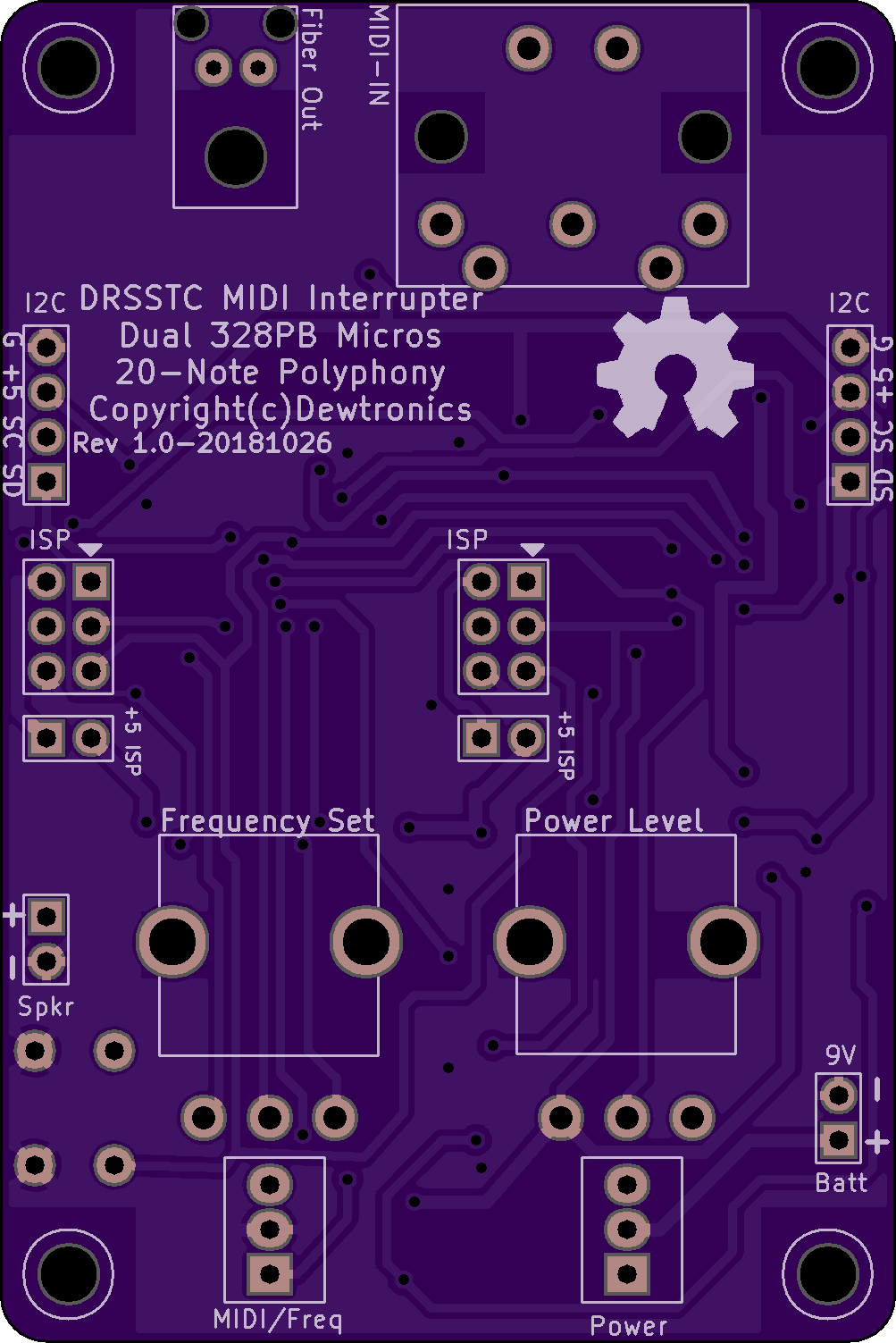
2 layer board of 2.01 x 3.01 inches (51.0 x 76.4 mm)
Uploaded:
November 05, 2018
Shared:
December 15, 2018
Total Price:
$30.15
MIDI Interrupter for Dual-Resonance Solid-State Tesla Coil using dual ATmega328PB micros for 20-note polyphony. This is a more compact alternative to the Quad-ATmega328P 24-note interrupter.
This board has been displaced by the better [Dual-Resonance Solid-State Tesla Coil MIDI Interrupter ST…
MIDI Interrupter for Dual-Resonance Solid-State Tesla Coil using dual ATmega328PB micros for 20-note polyphony. This is a more compact alternative to the Quad-ATmega328P 24-note interrupter.
This board has been displaced by the better Dual-Resonance Solid-State Tesla Coil MIDI Interrupter STM32F103 board.
Show full description
MIDI Interrupter for Dual-Resonance Solid-State Tesla Coil using dual ATmega328PB micros for 20-note polyphony. This is a more compact alternative to the Quad-ATmega328P 24-note interrupter.
This board has been displaced by the better [Dual-Resonance Solid-State Tesla Coil MIDI Interrupter ST…
MIDI Interrupter for Dual-Resonance Solid-State Tesla Coil using dual ATmega328PB micros for 20-note polyphony. This is a more compact alternative to the Quad-ATmega328P 24-note interrupter.
This board has been displaced by the better Dual-Resonance Solid-State Tesla Coil MIDI Interrupter STM32F103 board.
Show full description
-
Actions
- Order Board
- Download
- Permalink
- Embed link
Ordering shared project
Hey there! Before ordering, make sure you have all the info you need to complete and use this design. This usually means a component list, and sometimes additional information such as assembly notes, source code, or usage guides.Since this is a project designed by a community member, it may contain design errors that prevent it from working as intended. OSH Park cannot place any guarantees about the functionality or correctness of the design.
Wall-Clock Joule Thief V1
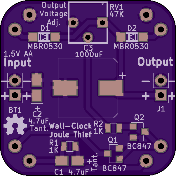

2 layer board of 1.21 x 1.21 inches (30.6 x 30.6 mm)
Uploaded:
June 23, 2018
Shared:
June 23, 2018
Total Price:
$7.25
This is an implementation of Lionel Sear's Wall-Clock Joule Thief circuit, found here: https://rimstar.org/science_electronics_projects/joule_thief_powering_clock_ls.htm and described by him in [this YouTube Vid…
This is an implementation of Lionel Sear’s Wall-Clock Joule Thief circuit, found here: https://rimstar.org/science_electronics_projects/joule_thief_powering_clock_ls.htm and described by him in this YouTube Video. And featured in this Hackaday Blog.
The circuit itself makes sense and should work in theory. I’m tired of replacing batteries in my wall-clocks so often and figured I’d give it a go.
The reference designators on this board are the same as in the original circuit at the above link. I did, however, use BC847 transistors instead of the BF546B specified on his original circuit. You should be able to use any similar NPN transistor. For C1 and C2, I opted for tantalum parts to make a smaller footprint. Those are Case-A 1206 size. Their ESR is slightly lower than electrolytics would be, but I believe will be a negligible change. For the diodes, I selected MBR0530 parts since I had them on-hand and they are low voltage-drop schottky type. You should be able to use any similar diode there, such as a LL4148. The resistors are 0805 footprint and the potentiometer is a Bourns 3362 series part.
The toroid I selected was a Magnetics, Inc. ZJ-42206-TC part, found on eBay. I selected that one because of its high permeability and small size (and inexpensive eBay price). Similar spec parts would be the following from Mouser (623-5975001801, 871-B64290L0638X035, and 871-B64290L0638X830).
The toroid mounts on the backside of the board. And assuming I’ve interpreted the toroid windings correctly, the four winding connection points are labeled 1 through 4 with the start-winding connection on “A” and the end-winding connection on “B”. In other words winding 1’s start would connect to “1A” and its ending would connect to “1B”. And so on for the remaining three windings.
UPDATE: This circuit does indeed work, at least electrically. And it does suck the last bit of juice out of a “dead” battery, ending at around 0.5 volts (0.523volts on my first test), just as Lionel said it would. However, it does NOT prolong battery life in general. The big design flaw in Lionel’s circuit seems to revolve around the output voltage limiter circuit, which turns off the Joule Thief by shunting the input through a 1K resistor via an NPN transistor.
This means the circuit draws approximately 1mA continuously. Lionel himself explained that 1mA draw in his video, found at the above links. Unfortunately, a continuous 1mA load is quite large for any small battery circuit that’s expected to run for a prolonged period.
Present testing of this circuit on several different wall-clocks and several identical circuit assemblies has shown an average of about 2-½ months life from a new AA battery with this Joule Thief. That, compared to a minimum of six months to a year with just the battery itself in the same wall-clock without the Joule Thief.
So feel free to build and experiment with this circuit, but don’t expect any “free-energy” nor prolonged battery life from it. I’m planning to investigate some circuit changes to replace that shunt regulation with a switch style regulation and use a PNP transistor to turn on the Joule Thief when charge is needed rather than the NPN shunting it off when it’s not.
Show full description
-
Actions
- Order Board
- Download
- Permalink
- Embed link
Ordering shared project
Hey there! Before ordering, make sure you have all the info you need to complete and use this design. This usually means a component list, and sometimes additional information such as assembly notes, source code, or usage guides.Since this is a project designed by a community member, it may contain design errors that prevent it from working as intended. OSH Park cannot place any guarantees about the functionality or correctness of the design.
- SERVICES
- Upload Your File
- Prototypes
- HELP
- Support
- If you can't find what you're looking for, please contact us at [email protected]
- CONNECT
- Shared Projects
- Log in / Sign up
