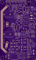
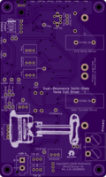
Dual-Resonance Solid-State Tesla Coil Driver V1
author: dewhisna
2 layer board of 3.01 x 5.01 inches (76.4 x 127.2 mm)
Uploaded:
May 30, 2018
Shared:
May 30, 2018
Total Price:
$75.20
NOTE: This board has been replaced by DRSSTC Driver V2.
Driver board for a Dual-Resonance Solid-State Musical Tesla Coil. This design features a zero-current-switching phase-lead circuit, an over-current detection/lockout circuit, an under-voltage lockout circuit, and a PLL-based adjustable dead-time delay. Requires regulated 15VDC power supply. It’s designed to be used with the Dual-Resonance Solid-State Tesla Coil Full Bridge board.
Drive two of these with the FPGA-Based Dual-Resonance Solid-State Stereo Music Tesla Coil Interrupter.
The debut performance for this board was during Shock-or-Treat Halloween 2018, and can be viewed at: http://mediadrop.dewtronics.com/media/media/shock-or-treat-halloween-2018.
Note: This board is still in the prototyping/testing phase and hasn’t been fully qualified yet. Build at your own risk.
Errata: Oops, just realized I goofed the via hole size. They were supposed to be 25mil, but are 35mil instead. The vias are 46mil diameter, so it’s still within fabrication specs, but just barely. I hate cutting things that close to minimum tolerance specs.
Also, resistor R5 should be a 330-Ohm instead of 470-Ohm to allow the Blue LED to be a little brighter, as Blue LEDs require more current. And, the 1K-Ohm R9 should be at least a ½-Watt part and preferably 1-Watt, or you will risk burning it up from the high-voltage peaks of the current-transformer in the zero-current-switching circuit, which occurred during the first static-load test performed on this board. Unfortunately, finding such a large wattage part in a 0805 footprint will be difficult, if not impossible, meaning a large through-hole part will have to be graft in.

