DRSSTC Bridge V2.1

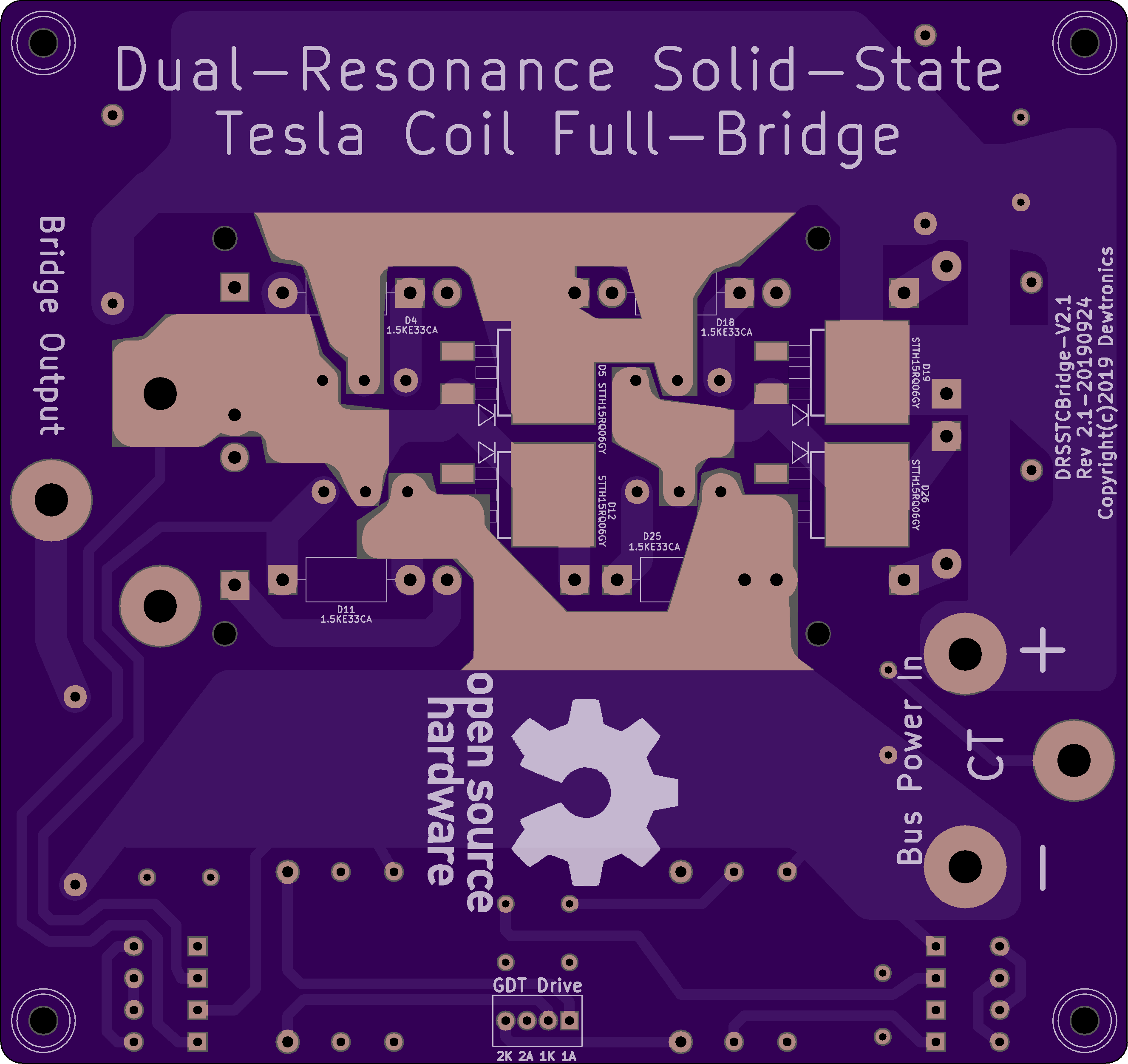
2 layer board of 5.31 x 5.01 inches (134.8 x 127.2 mm)
Uploaded:
September 27, 2019
Shared:
September 28, 2019
Total Price:
$132.80
Dual Resonance Solid-State Tesla Coil Full-Bridge V2.1. Replaces the older V2 version. This version uses larger barrier connectors and has wider feeder traces with solder-mask to allow for reflow-solder to increase current capacity. Suggested to …
Show full description
Dual Resonance Solid-State Tesla Coil Full-Bridge V2.1. Replaces the older V2 version. This version uses larger barrier connectors and has wider feeder traces with solder-mask to allow for reflow-solder to increase current capacity. Suggested to …
Show full description
AN3813K PID LCD Shield Host Board V1
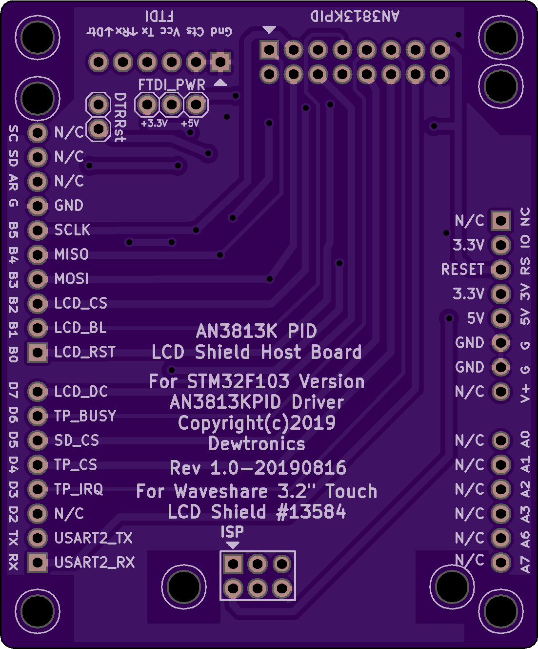
2 layer board of 2.21 x 2.66 inches (56.0 x 67.5 mm)
Uploaded:
August 17, 2019
Shared:
August 17, 2019
Total Price:
$29.25
LCD Shield Host Board for the AN3813K BLDC VCR Cylinder Motor Driver Arduino Shield PID Version V2 board. Designed for use with the Waveshield 3.2" Touch LCD Shield #13584.
LCD Shield Host Board for the AN3813K BLDC VCR Cylinder Motor Driver Arduino Shield PID Version V2 board. Designed for use with the Waveshield 3.2" Touch LCD Shield #13584.
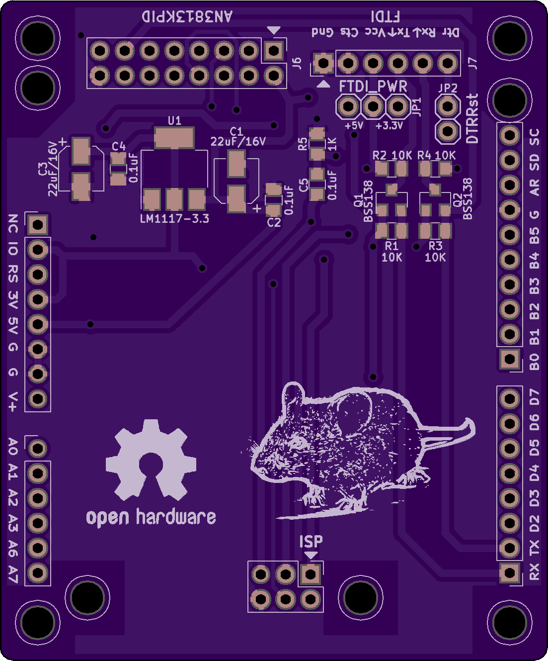
AN3813K BLDC VCR Cylinder Motor Driver Arduino Shield PID Version V2
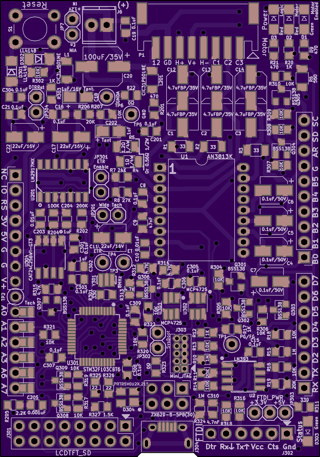
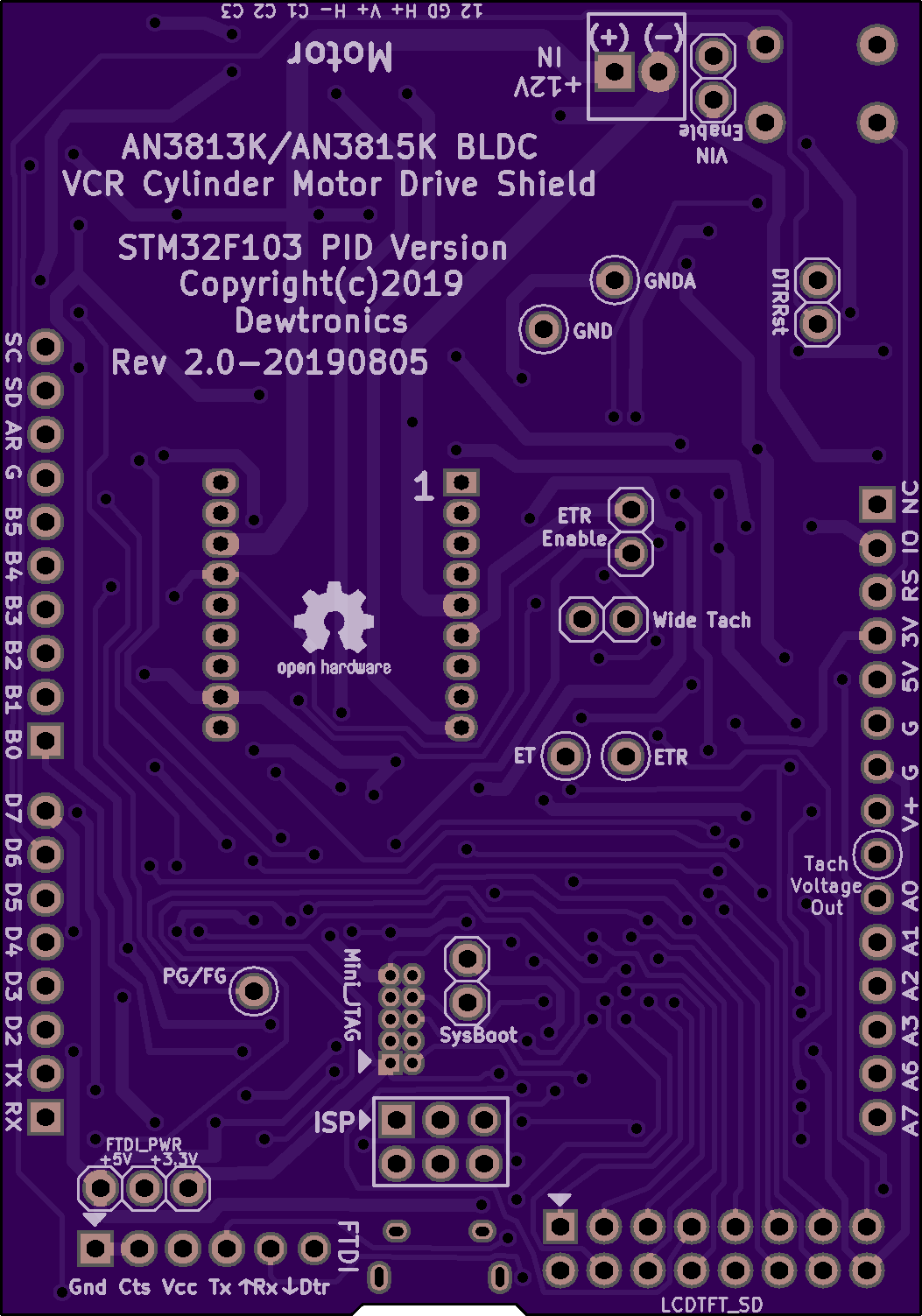
2 layer board of 2.11 x 3.01 inches (53.5 x 76.4 mm)
Uploaded:
August 16, 2019
Shared:
August 17, 2019
Total Price:
$31.65
This is the STM32F103 replacement for the AN3813K BLDC VCR Cylinder Motor Driver Arduino Shield PID Version V1 board.
PID Loop version of the AN3813K Brushless DC Motor Driver Arduino Shield for use with VCR Cylinder Motors. PID Loop Control done…
Show full description
This is the STM32F103 replacement for the AN3813K BLDC VCR Cylinder Motor Driver Arduino Shield PID Version V1 board.
PID Loop version of the AN3813K Brushless DC Motor Driver Arduino Shield for use with VCR Cylinder Motors. PID Loop Control done…
Show full description
MIDI Theremin using STM32F103C8T6 Blue Pill V1
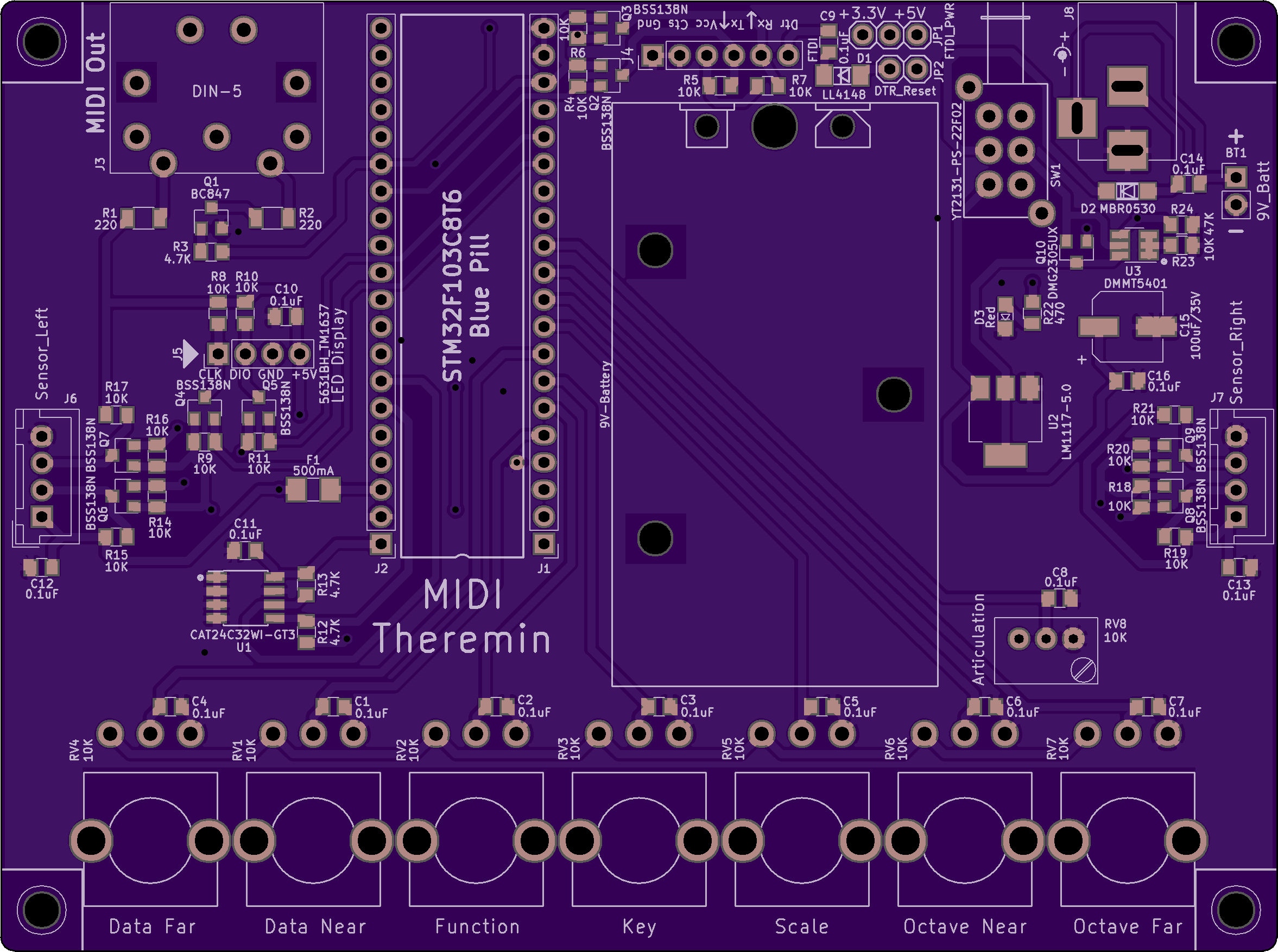
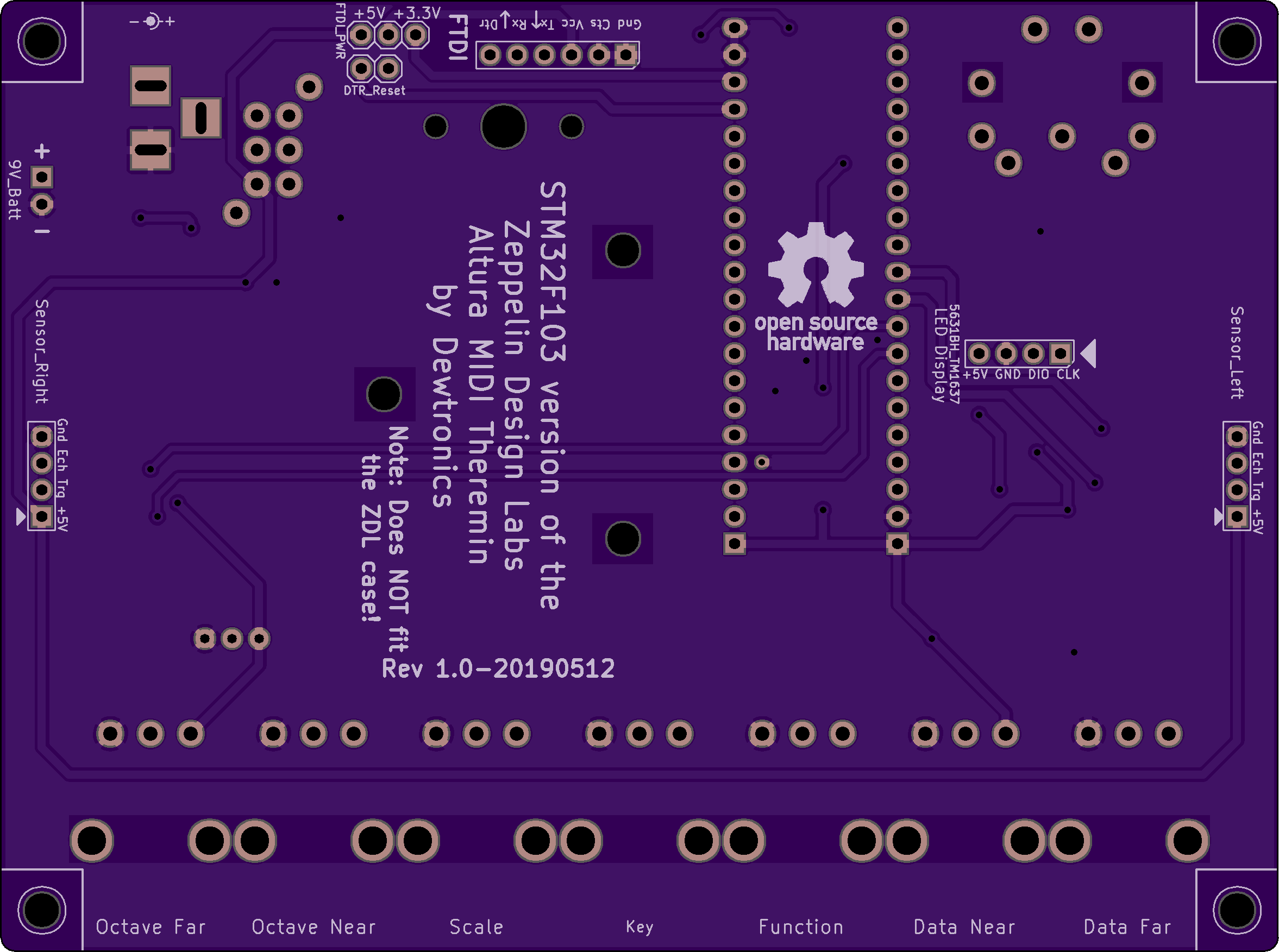
2 layer board of 4.71 x 3.51 inches (119.5 x 89.0 mm)
Uploaded:
May 28, 2019
Shared:
July 09, 2019
Total Price:
$82.45
STM32F103C8T6 "Blue Pill" version of the Zeppelin Design Labs Altura MIDI Theremin.
Details on this remix, including source code, schematics, bill-of-materials, and 3D Printed case files, can be found on GitHub.
ERRATA: The MIDI Out DI…
Show full description
STM32F103C8T6 "Blue Pill" version of the Zeppelin Design Labs Altura MIDI Theremin.
Details on this remix, including source code, schematics, bill-of-materials, and 3D Printed case files, can be found on GitHub.
ERRATA: The MIDI Out DI…
Show full description
3-Digit 7-Segment LED 5631BH Board with TM1637 Driver
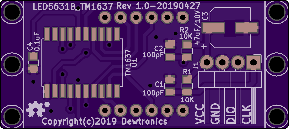
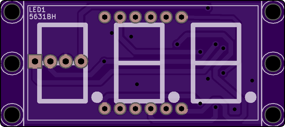
2 layer board of 1.86 x 0.83 inches (47.1 x 21.1 mm)
Uploaded:
April 28, 2019
Shared:
April 28, 2019
Total Price:
$7.70
This is a compact 3-Digit 7-Segment LED Display board, which uses the 5631BH Common Anode LED Display with the Titan Micro TM1637 LED Driver Chip. It is very similar to the many off-the-shelf variations, but is slightly more compact in that it has 3-Digits instead of 4-Digits, as most of-the-she…
Show full description
