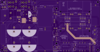
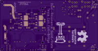
Dual-Resonance Solid-State Tesla Coil Full Bridge V1
author: dewhisna
2 layer board of 9.66 x 5.01 inches (245.3 x 127.2 mm)
Uploaded:
May 29, 2018
Shared:
May 30, 2018
Total Price:
$241.65
NOTE: This board has been replaced by DRSSTC Bus Supply V1 and DRSSTC Bridge V2 as a modular pair.
Full-Bridge power circuit for running a small desktop Musical Tesla Coil from 110/120 VAC. This design features a Soft-Start power-up circuit and relay controlled power-off voltage bleeder circuit. Note: Soft-Start and power rectification circuits are NOT compatible with 220/240 VAC! Recommend using 2oz Copper.
This board is designed to be driven by the Dual-Resonance Solid-State Tesla Coil Driver board.
The debut performance for this board was during Shock-or-Treat Halloween 2018, and can be viewed at: http://mediadrop.dewtronics.com/media/media/shock-or-treat-halloween-2018.
Note: This board is still in the prototyping/testing phase and hasn’t been fully qualified yet. Build at your own risk.
ERRATA: Do NOT build this circuit as-is. The soft-start circuit has a design flaw that causes SCR (D29) to false trigger early and to “bounce”, which causes the Soft-Start Relay RL1 to chatter and fuse its contacts due to the high inrush current, ruining the relay. The high inrush current will then fry one or both mains input rectifier diodes D32 and/or D33, and then blow the fuse.
If building, do not install the following components: RL1, D29, D30, D31, R5, R6, R7, R8, R9, RV1, C2, and R14. In the place of R14, install a NTC Thermistor Inrush Current Limiter, such as Ametherm MS22-10008 (DigiKey: 570-1003-ND) – note that this can be installed between pads 41 and 44 of the RL1 footprint for closer pin spacing, but give it plenty of air space and ventilation, as it will get hot. You can also use a variac to slowly bring up power to the entire circuit – but you’ll need to start it at around 70 volts to keep the Bleeder Relay RL2 from chattering.
Also, resistor R10 needs to be a sufficiently high wattage part. It will have about a 155-160Volt drop at 3.3mA, which is 530mW. So, use at least a 3/4Watt resistor for R10 or risk it leaking its “magic smoke”.
Note that at circuit power-down, resistor R15 will get a little toasty. This is normal. However, your driving circuit should monitor the ‘fault’ pin (pin 3 of J1) and shutdown all AC input if the fault condition (i.e. Relay RL2 open) exists for more than a few seconds, as the 2.5W rating of R15 is only sufficient as a bleeder resistor for the system. A continuous load resistor of that value would have to be around 120Watts. If the 2.5W part was left in the circuit very long (longer than the required voltage bleed down period), it would either burn in two or catch fire.
Also, cut the copper-pour trace for the ground fill where it runs underneath the fuse holder. Failure to do this will cause a short between the 120VAC mains and ground under the 120VAC-input end of the fuse holder when the solder-mask gets breached beneath it. Apparently, I should have made the area under the fuse a keepout-area for that copper pour. It is, however, a self-correcting problem, because when it shorts, the trace, and select parts of the fuse holder, will vaporize. But it is a rather loud and startling bang, and you’ll probably have to reset the circuit breaker for your power feed.

