EEPROM Board for STM32F746G Discovery V1
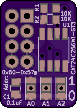
2 layer board of 0.51 x 0.71 inches (12.8 x 17.9 mm)
Uploaded:
April 13, 2019
Shared:
April 14, 2019
Total Price:
$1.75
EEPROM Add-on Board for the STM32F746G Discovery board via the EXT I2C connector.
EEPROM Add-on Board for the STM32F746G Discovery board via the EXT I2C connector.
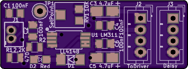
DRSSTC Bus Supply V2
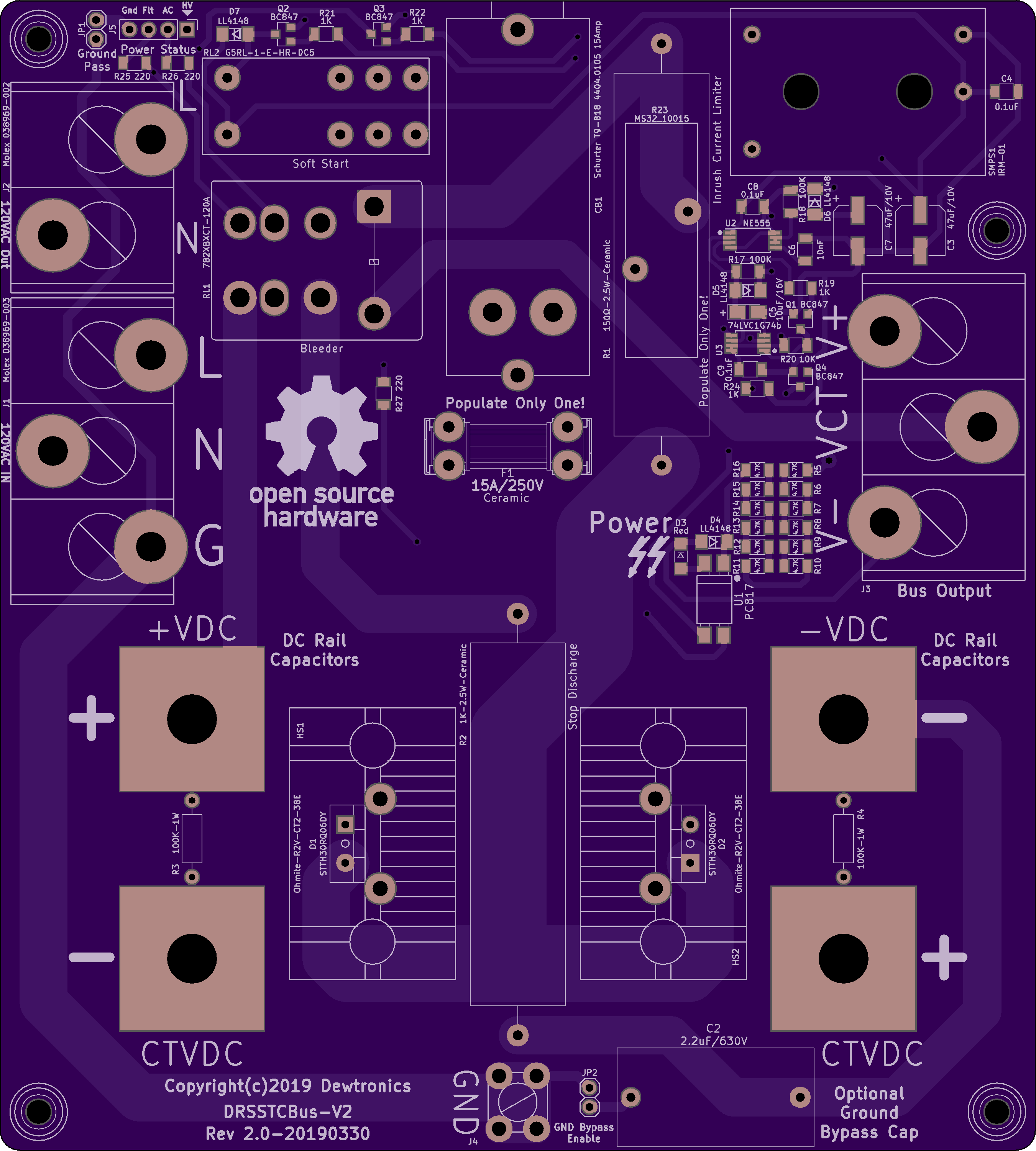

2 layer board of 5.41 x 6.01 inches (137.3 x 152.6 mm)
Uploaded:
April 05, 2019
Shared:
April 05, 2019
Total Price:
$162.30
Dual-Resonance Solid-State Tesla Coil 340VDC Bus Supply (from 120VAC only).
This version is designed to be used with large electrolytic capacitors, such as Cornell-Dubilier 500C series screw-terminal mount. The prototype circuit is using two 10,000uF 450VDC Cornell-Dubilier 500C series capacit…
Show full description
Dual-Resonance Solid-State Tesla Coil MIDI Interrupter STM32F103 V1
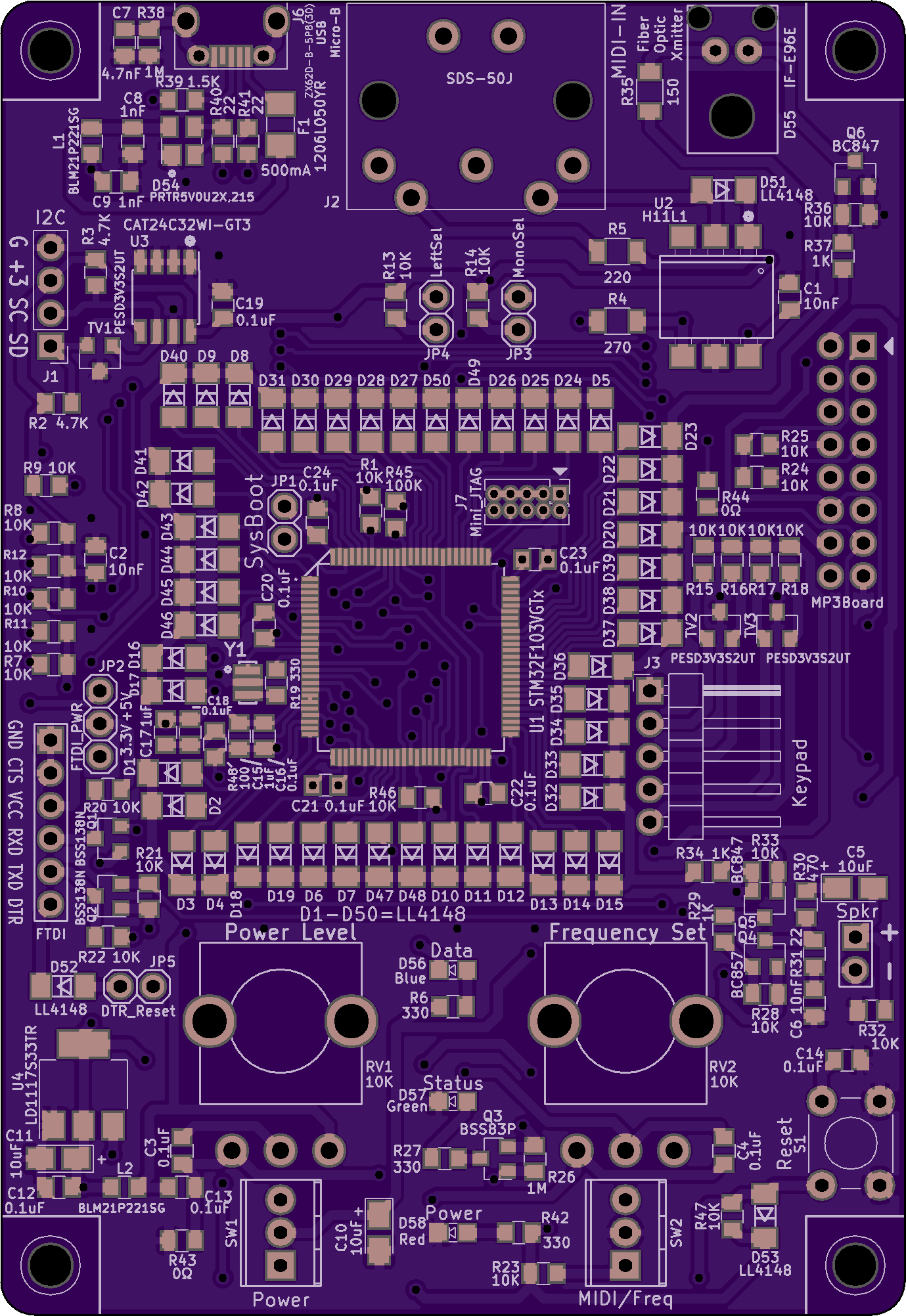
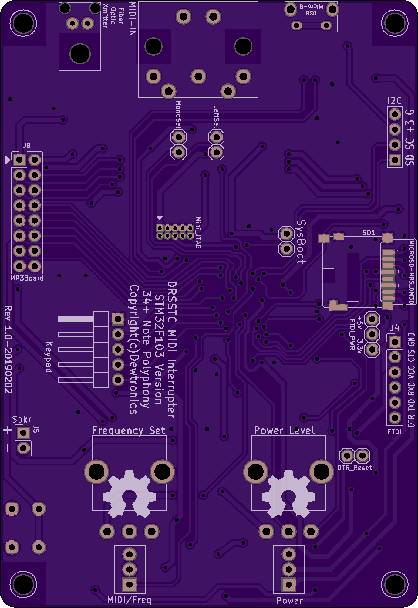
2 layer board of 2.76 x 4.01 inches (70.0 x 101.8 mm)
Uploaded:
February 25, 2019
Shared:
March 25, 2019
Total Price:
$55.20
STM32F103 version of Dual-Resonance Solid-State Tesla Coil MIDI Interrupter. Designed for 34+ note polyphony (up to 50 note polyphony if using clever timer tricks).
This design replaces the older [Dual-Resonance Solid-State Tesla Coil MIDI Interrupter Dual 328PB](https://oshpark.com/shared_pr…
Show full description
DRSSTC Thermal Limiter Board V1
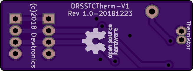
2 layer board of 1.31 x 0.48 inches (33.2 x 12.2 mm)
Uploaded:
December 24, 2018
Shared:
March 01, 2019
Total Price:
$3.10
Dual-Resonance Solid-State Tesla Coil Thermal Limiter Board V1. For use with the Dual Resonance Solid-State Tesla Coil Driver V2.
Dual-Resonance Solid-State Tesla Coil Thermal Limiter Board V1. For use with the Dual Resonance Solid-State Tesla Coil Driver V2.
DRSSTC Bus Caps V2
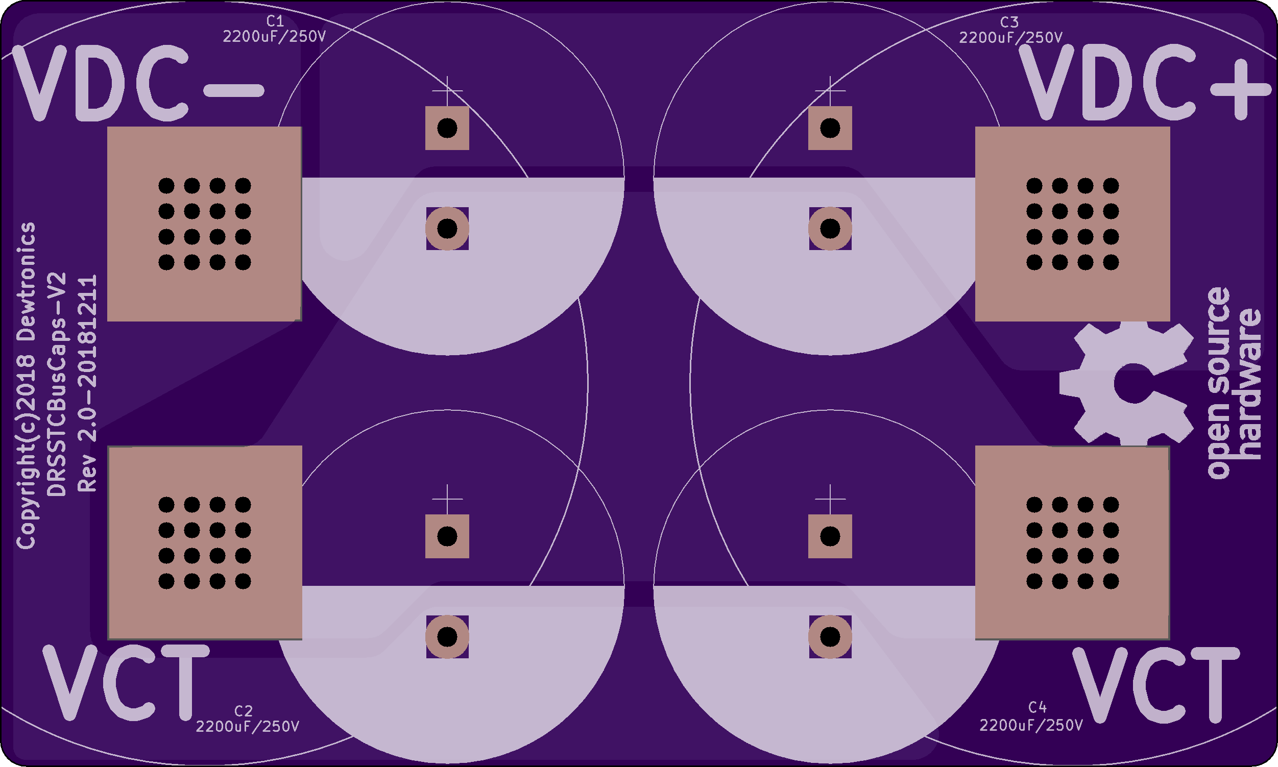
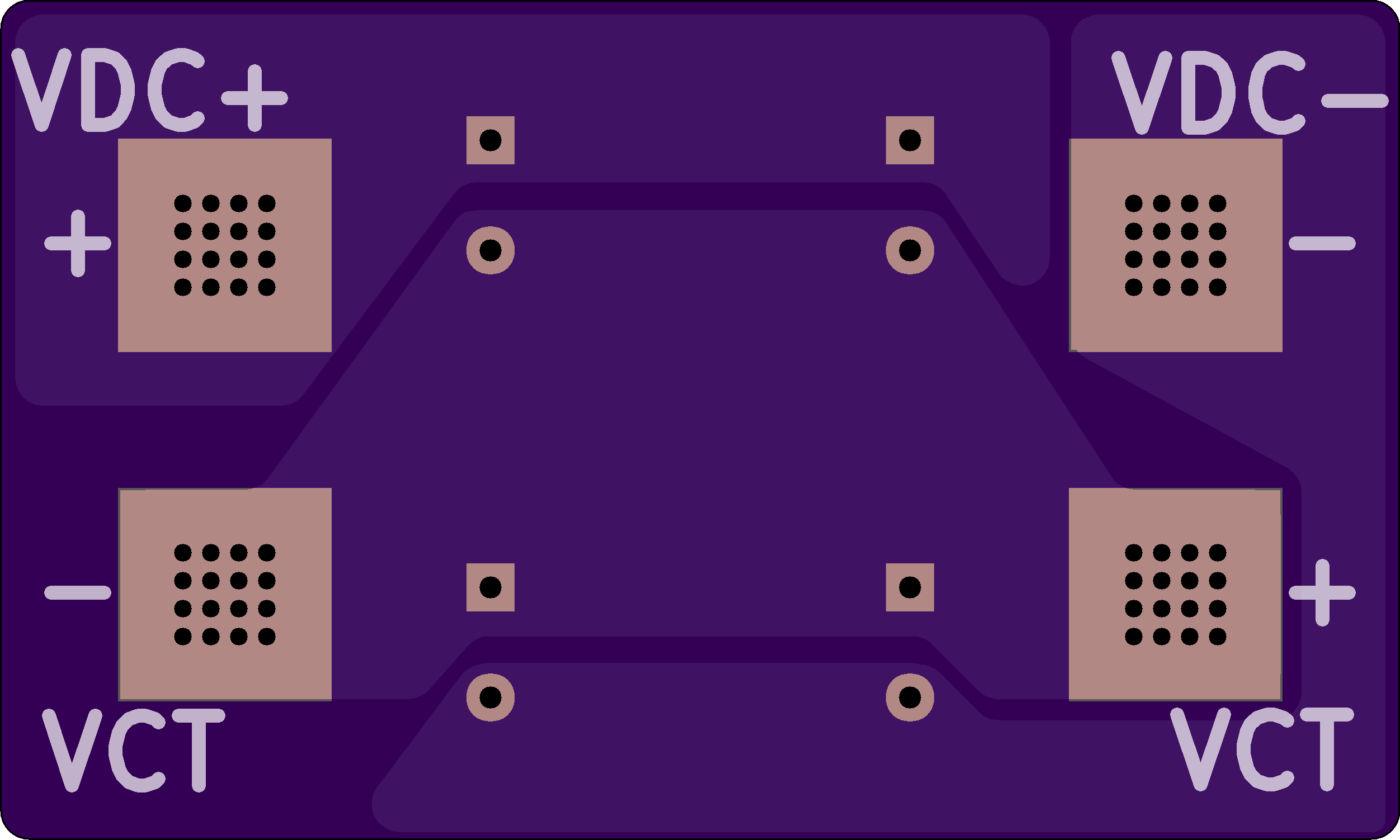
2 layer board of 5.01 x 3.01 inches (127.2 x 76.4 mm)
Uploaded:
December 24, 2018
Shared:
March 01, 2019
Total Price:
$75.20
Dual-Resonance Solid-State Tesla Coil Bus Capacitor Board V2. Used for mounting smaller, through-hole, bus caps to the DRSSTC Bus Supply V1 board. Requires 710-7461097 : Würth Terminals WP-BUFU Pin-Plate 16Pin Bush M6 180A.
Dual-Resonance Solid-State Tesla Coil Bus Capacitor Board V2. Used for mounting smaller, through-hole, bus caps to the DRSSTC Bus Supply V1 board. Requires 710-7461097 : Würth Terminals WP-BUFU Pin-Plate 16Pin Bush M6 180A.
