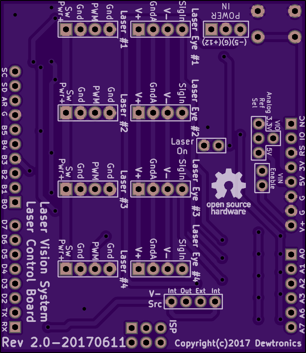
Laser Vision System - Laser Control Board V2
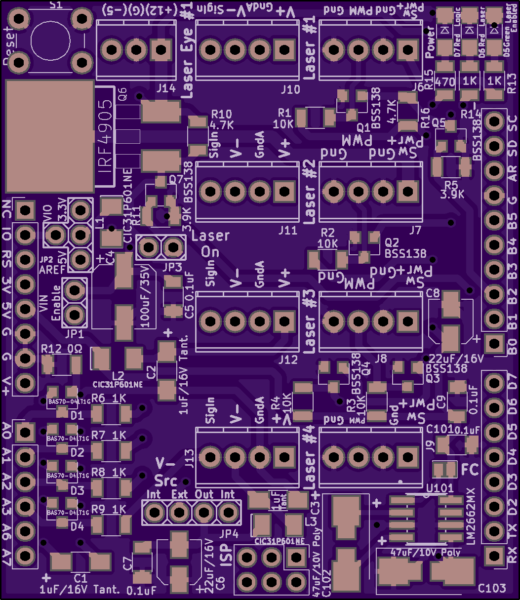
2 layer board of 2.11 x 2.43 inches (53.5 x 61.8 mm)
Uploaded:
June 27, 2017
Shared:
June 27, 2017
Total Price:
$25.55
Laser Control Board Arduino Shield for the Laser Vision System. This board interfaces the laser PWM power modulation and on/off logic, as well as the LaserEye Reflection Sensors.
Version 2 with fixed voltage inverter circuit and corrections in power switching logic, changing it to switch the h…
Show full description
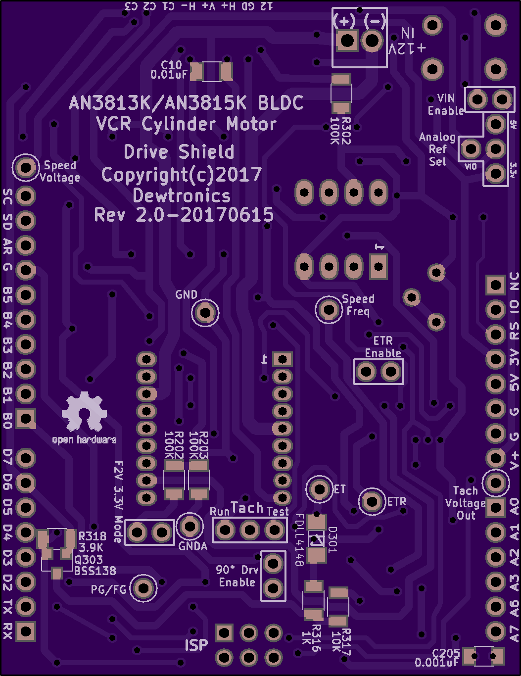
AN3813K BLDC VCR Cylinder Motor Driver Arduino Shield V2
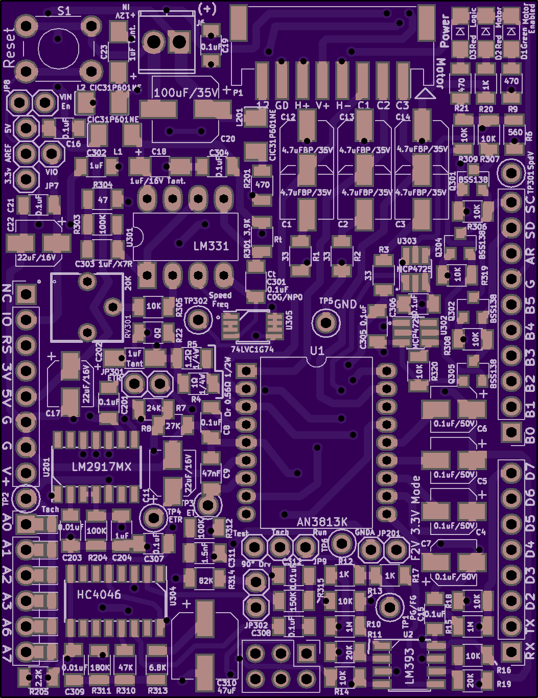
2 layer board of 2.11 x 2.73 inches (53.5 x 69.4 mm)
Uploaded:
June 23, 2017
Shared:
June 23, 2017
Total Price:
$28.75
Version 2 of AN3813K Brushless DC Motor Driver Arduino Shield (PLL Version) for use with VCR Cylinder Motors with precision speed control with feedback.
Specifically designed to be used with the Arduino ProMini PiDuino HAT and the STM32F746G …
Show full description
Version 2 of AN3813K Brushless DC Motor Driver Arduino Shield (PLL Version) for use with VCR Cylinder Motors with precision speed control with feedback.
Specifically designed to be used with the Arduino ProMini PiDuino HAT and the STM32F746G …
Show full description
Raspberry Pi Power Feed HAT

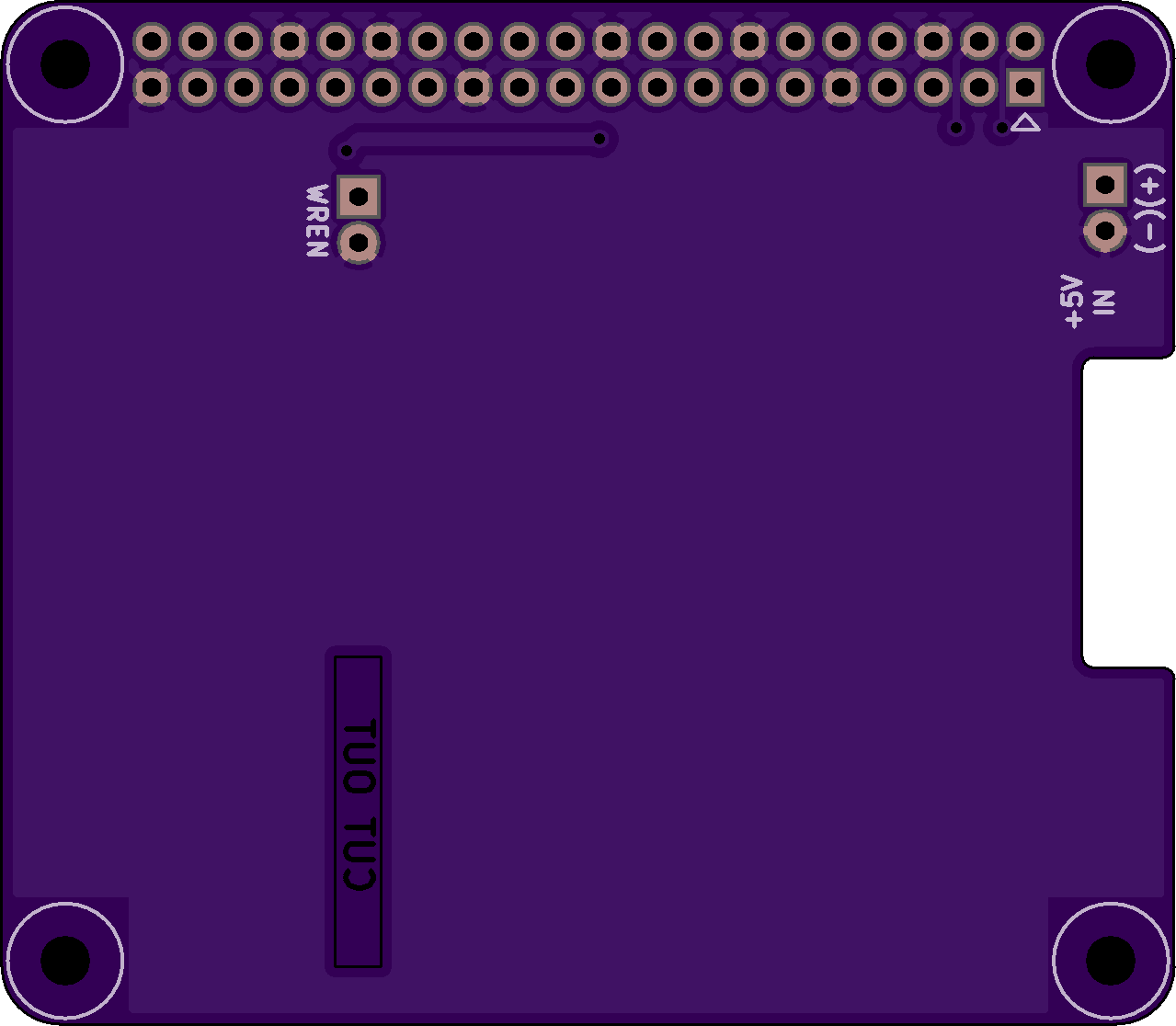
2 layer board of 2.56 x 2.23 inches (64.9 x 56.7 mm)
Uploaded:
June 18, 2017
Shared:
June 18, 2017
Total Price:
$28.50
Simple Raspberry Pi HAT Board that provides the backfeed protection logic to power a Raspberry Pi board from an external +5V lab-grade power supply, as per the Raspberry Pi HAT Specs and the [ZVD Circuit](https://github.com/raspberrypi/hats/blob/master/zvd-c…
Show full description
Simple Raspberry Pi HAT Board that provides the backfeed protection logic to power a Raspberry Pi board from an external +5V lab-grade power supply, as per the Raspberry Pi HAT Specs and the [ZVD Circuit](https://github.com/raspberrypi/hats/blob/master/zvd-c…
Show full description
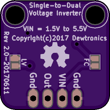
Single-to-Dual Voltage Converter V2
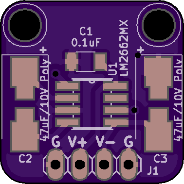
2 layer board of 0.76 x 0.76 inches (19.2 x 19.2 mm)
Uploaded:
June 11, 2017
Shared:
June 11, 2017
Total Price:
$2.85
Charge-pump circuit to create a negative tracking split supply voltage that mirrors the single supply input voltage. This voltage inverter version uses the LM2662 and VIN must be between 1.5v and 5.5v.
Charge-pump circuit to create a negative tracking split supply voltage that mirrors the single supply input voltage. This voltage inverter version uses the LM2662 and VIN must be between 1.5v and 5.5v.
SDIP018-P-0550 Adapter
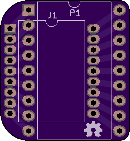
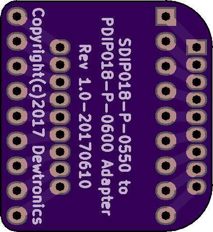
2 layer board of 0.86 x 0.93 inches (21.7 x 23.6 mm)
Uploaded:
June 11, 2017
Shared:
June 11, 2017
Total Price:
$3.95
18-Pin Shrunk DIP 0.550", 0.070" pitch (13.97mm, 0.1778mm pitch) (SDIP018-P-0550) Adapter to convert it to 18-Pin Wide DIP 0.600", 0.100" pitch (15.24mm, 2.54mm pitch)
18-Pin Shrunk DIP 0.550", 0.070" pitch (13.97mm, 0.1778mm pitch) (SDIP018-P-0550) Adapter to convert it to 18-Pin Wide DIP 0.600", 0.100" pitch (15.24mm, 2.54mm pitch)
