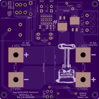
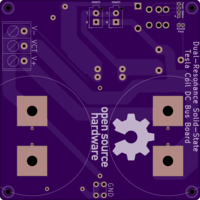
DRSSTC Bus Supply V1
author: dewhisna
2 layer board of 5.01 x 5.01 inches (127.2 x 127.2 mm)
Uploaded:
December 24, 2018
Shared:
March 01, 2019
Total Price:
$125.30
Dual-Resonance Solid-State Tesla Coil 340VDC Bus Supply (from 120VAC only).
NOTE: This board has been replaced by the newer DRSSTC Bus Supply V2 design!
This version is designed to be used with large electrolytic capacitors, such as Cornell-Dubilier 500C series screw-terminal mount. The prototype circuit is using two 10,000uF 450VDC Cornell-Dubilier 500C capacitors. Or optionally, you can use the DRSSTC Bus Caps V2 board to mount smaller, through-hole, bus caps to this board using 710-7461097 : Würth Terminals WP-BUFU Pin-Plate 16Pin Bush M6 180A.
ERRATA: LED D3 and Opto-Isolator U1 cannot both be populated or else only one of the two will function, based on their required voltage drop. Both are designed as “HV Power On” indicators, only one is on-board and the other is remote. Decide if you want your indicator on-board or remote and populate accordingly. OR, you can modify the circuit so that D3 and U1 are in series instead of parallel. For that, cut the two traces leading from D4 to D3, and place a jumper between the anode of D4 (the LL4148) and the cathode of D3 (the visible LED). That will place the LED internal to the U1 Opto-Isolator in series with the visible LED D3 and allow both to function correctly (this is the preferred fix).
This board, along with the DRSSTC Bridge V2 replace the original DRSSTC Bridge V1.

