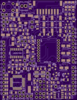
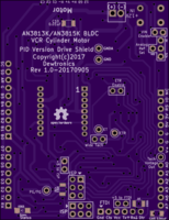
AN3813K BLDC VCR Cylinder Motor Driver Arduino Shield PID Version V1
author: dewhisna
2 layer board of 2.11 x 2.73 inches (53.5 x 69.4 mm)
Uploaded:
September 08, 2017
Shared:
September 08, 2017
Total Price:
$28.75
PID Loop version of the AN3813K Brushless DC Motor Driver Arduino Shield for use with VCR Cylinder Motors. PID Loop Control done via on-board ATmega328 coprocessor. NOTE: This is a ATmega328PB. NOT a ATmega328P! The ‘B’ version micro is needed for the dual I2C interfaces as one is a master and one is a slave. The master communicates with the on-board DACs used to drive the AN3813K chip and the slave communicates with the main processor via the Arduino header pins.
See the AN3813K BLDC VCR Cylinder Motor Driver Arduino Shield V2 project for the PLL Version of this board. Both versions are viable solutions depending on preference of Analog PLL circuit or Digital PID via a microcontroller.
All smaller surface mount discrete parts are 1206 footprint except for the two 24pF capacitors for the crystal oscillator circuit for the micro (C307 and C308). Those two parts use 0805 footprints.
Note: Populate either C1-C3 with R1-R3 or populate C12-C14 without R1-R3. C1-C3 is a low-side filter and C12-C14 is a high-side filter. Only one set is needed. Preference is generally for C12-C14. In either case, those capacitors should be bipolar.
ERRATA: Atmel/Microchip recently decided to change the ATmega328PB (and its variants) to no longer support full-swing oscillator drive and therefore won’t drive the standard AT-cut crystal that this board was designed to use. In fact, I even discovered a bug in their die that if you use a crystal that almost starts but doesn’t quite, it can get into a mode where it switches back and forth between the internal oscillator and the external crystal and if you try to do flash reprogramming with it running in that mode, it will drive the charge pumps too long and fry the flash cells, destroying the chip. I accidentally fried one of my ATmega328PB chips this way.
Therefore, do NOT populate the Y301 crystal, the C307 or C308 capacitors, or the R312 resistor. And instead, set the low-fuse byte to 0xE2 to enable the internal 8 MHz RC oscillator at full speed. There is no good way, as it is currently designed, to attach a low-powered ceramic oscillator or even an external oscillator module to this board.
Perhaps a future version of this board will be spun to allow better oscillator options and higher speed operation. But, in all honesty, 8MHz is plenty fast, as the original design of this circuit, some eighteen years ago, was with a 68HC11 running at 4MHz, which since it was CISC instead of RISC, was less than an eighth of the speed of this ATmega328PB at 8MHz, and it was plenty fast.

