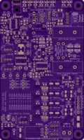
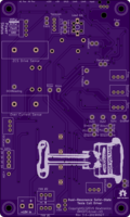
Dual Resonance Solid-State Tesla Coil Driver V3
author: dewhisna
2 layer board of 3.01 x 5.01 inches (76.4 x 127.2 mm)
Uploaded:
September 30, 2019
Shared:
September 30, 2019
Total Price:
$75.20
Driver board for a Dual-Resonance Solid-State Musical Tesla Coil. This version is a mix of the V1 Version and the V2 Version.
This version uses the original UCC37322 drivers (only in the MSOP-PowerPAD footprint instead) and runs on +15V like the V1, but includes the Skip Pulse and thermal limiter input logic from the V2.
The general layout also conforms to the V2 format and is designed to be mounted upright like the V2 instead of upside-down like the V1.
Note: Change RV2 and/or R20 to adjust the SG3525 PLL circuit for your coil’s resonant frequency. With the values of 2K for RV2 and 1K for R20, as labeled, it works for a coil with an approximate resonant frequency of 200-250kHz. Changing them, for example, to 10K for RV2 and 6.8K for R20, it works for a coil that’s approximately 45-100kHz. The exact range is dependent on the dead-time setting, as it alters the frequency slightly, and by component tolerance and circuit parasitics. Refer to the SG3525 datasheet for the frequency equations. Note that FreqOut is 2x the resonant frequency due to the SG3525 dividing the frequency for the dual outputs. The Free-Running frequency of the PLL should be set to about 5% less than 2x the primary circuit resonant.
ERRATA: There is a logic error in the lockout circuit that causes a race-condition with the U9 flip-flop (74LVC1G74) between the fiber-optic edge detect signal on the set-input and the main fiber-optic signal on the clock pin. This can cause the system to never start and results in only a short burst of output at the beginning of each interrupter pulse, and it also prevents the skip-pulse mode from working at all.
To resolve, the fiber optic input signal needs to be removed from pin 1 of U9. And the skip-pulse signal on pin 2 needs to move to pin 1. And pin 2 needs to get tied to +5v. To do this, cut the trace leading into pin 1 of U9 (leaving the 90-degree junction intact where it runs under U4), and cut the trace leading into pin 2 of U9 between U9 and resistor R52. Solder a jumper between pin 1 of U9 and R52, on the end where the trace to pin 2 was cut (this takes care of moving the skip-pulse signal from pin 2 to pin 1). And solder a small jumper wire to pin 2 of U9 that runs to +5v. The closest and probably most convenient point for +5v is the far end of capacitor C40, which is the power decoupling capacitor for U9. This jumper can be quite tricky as it has to solder to a single pin on a TSSOP package (0.65mm pin-spacing).
This errata will be resolved in V3.1.

