DRSSTC Data Acquisition Board V1
author: dewhisna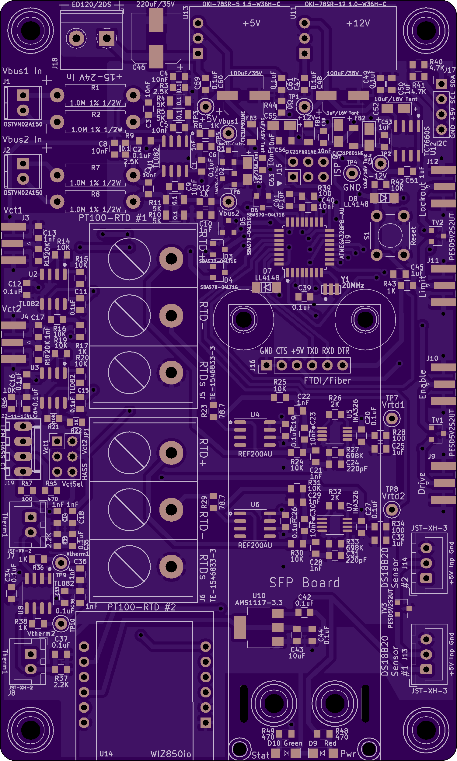
2 layer board of 3.01 x 5.00 inches (76.3 x 127.1 mm)
Uploaded:
March 22, 2021
Shared:
March 22, 2021
Total Price:
$75.15
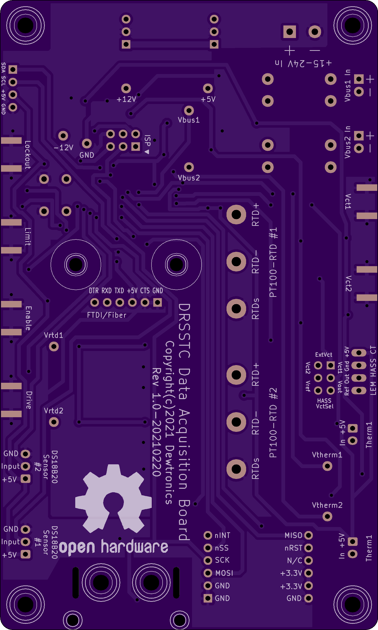
DRSSTC (Dual-Resonant Solid-State Tesla Coil) Data Acquisition Board V1 – designed to amend the DRSSTCDriver V1-V3 boards, such as this board to provide some of the data acquisition (DAQ) features of the future DRSSTCDriver V4 that will have integrated DAQ support.
This board is designed to be used with the SFP2TTL Small Form-Factor Pluggable Fiber Optic Transceiver to TTL V1 Board to provide a TTL to Fiber-Optic communications link to the PC and/or with a WIZ850io Ethernet interface.
The Vbus1 and Vbus2 analog inputs are differential 0-1000V inputs, designed to monitor the main DC power bus voltage for the Tesla Coil, measured via ADC0 and ADC1. Vct1 and Vct2 are single-ended 0-10V inputs, designed to monitor the current-sense transformer from the over-current-detector circuit of the Tesla Coil Driver circuit, measured on ADC2 and ADC3. Alternately, Vct1/Vct2 can be reassigned to a LEM HASS-series bi-directional hall-effect current-transducer, measuring its 0-5V output on the Vct1 channel and its Vref (2.5V) output on the Vct2 channel, based on jumper selection. There’s two high-precision instrumentation amplifier circuits to read PT100-RTD temperature sensors, measured on ADC4 and ADC5. There’s two low-precision thermistor temperature inputs, Therm1 and Therm2, designed for 10K 3950beta thermistors, measured via ADC6 and ADC7.
Digital inputs PB0 and PB1 are assigned to Drive and Enable signal inputs from the Tesla Coil Driver to measure the coil’s resonant frequency via Timer1. PD4 and PD5 are assigned to Lockout and Limit signal inputs from the Tesla Coil Driver to monitor lockout/limit event triggers. PD6 and PD7 are assigned to single-wire DS18B20 digital temperature sensors.
ERRATA: The two DS18B20 ports are missing the required 4.7K pull-up resistor to +5V on their data I/O line. These can be added by placing a 4.7K 0805 SMD resistor across pins 1 and 2 on both J13 and J14.
A copy-and-paste error in the silkscreening for J8 has it incorrectly labeled as ‘Therm1’ instead of ‘Therm2’ (on both top and bottom).
