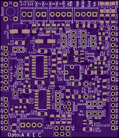
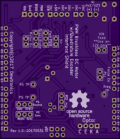
PWM BLDC Motor w/Quadrature Encoder Interface Shield V1
author: dewhisna
2 layer board of 2.11 x 2.43 inches (53.5 x 61.8 mm)
Uploaded:
June 03, 2017
Shared:
June 03, 2017
Total Price:
$25.55
This design has been replaced with Version 2: https://www.oshpark.com/shared_projects/QzN0O7fN.
This is an Arduino Compatible Interface Shield for interfacing with Blushless DC (BLDC) Motors having their own 3-Phase controllers with a PWM Speed Set Input. It supports either a two-signal 90-deg quadrature speed sensor or a 3-Phase Hall-Effect speed sensor input. It has support for an optical reflectivity sensor for Zero-Position/Index sensing or it can use an external Z-Pos Index Sensor. Supports both 3.3V and 5V logic with on-board level shifters.
ERRATA: The silkscreen labeling for the ‘direct’ vs ‘opto’ modes on the Z-phase source selection jumper JP6 are backwards. The pin marked ‘direct’ is the ‘opto’ input and the pin marked ‘opto’ is the ‘direct’ input. Also, I forgot to add a ‘ground’ test-point pin. Otherwise, everything works as expected. The Z-phase optical reflectivity sensor design on this board, unfortunately, is too slow and unresponsive for most motor applications. This version has been replaced with version 2 https://www.oshpark.com/shared_projects/QzN0O7fN, which allows for a faster reflectivity sensor input design, plus supports a hall-effect Z-phase input.

