Dragon Lair #2
author: strongeye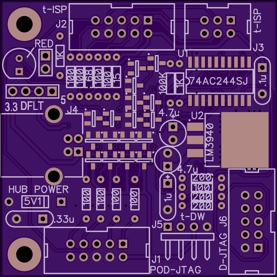

2 layer board of 2.11 x 2.11 inches (53.5 x 53.5 mm)
Uploaded:
August 30, 2015
Shared:
September 04, 2015
Total Price:
$22.15
This is a rendition of the Dragon Lair board by Nard at: http://www.aplomb.nl/TechStuff/Dragon/Dragon.html
The POD-JTAG connector, J1, is not pinned out for standard JTAG pin sequence but is based on the improved signal integrity pin out as described by Kasper (KKP) in this document: http://n1.taur.dk/permanent/dragonhide.pdf
A small descrambler board at the end of the JTAG cable in the vicinity of the target IS REQUIRED to rearrange the signal sequencing for standard pin-out JTAG connectors. This descrambler is a very simple board and can be implemented with a small vector/vero board type circuit as a POD at the end of the ribbon cable. See Kasper’s .pdf document for information. An example of this board is available from my projects and is called DRAGON LAIR JTAG CABLE POD.
This is a protection/buffer board for the Atmel AVR Dragon programmer board that has some weaknesses due to cost constraints in Atmel’s design of the AVR Dragon. As in the designs by Kasper and Nard, there is no provision on this board for high voltage programming, which is possible on the Dragon. Be careful if you use the high voltage programming for resetting fuses and refer to the Atmel documentation. DO NOT USE this board for that application.
This is for the second version of the Dragon that has the mounting holes for mechanical purposes but it should be able to be used by the earlier version if mounting is done with some sort of sticky foam tape, etc.. This board piggy-backs over the Dragon and has a USB2.0 type B connector for power only oriented just above the USB2.0 type B of the Dragon. The Dragon needs to be powered by a powered USB HUB anyway, and this board optionally can be powered by another port of the same HUB if the target board is not to be self powered. Three selectable hub powered voltage regimes are allowed: +3.3V, +5V, and default target self-powered and these are pin strap selectable with the left 2 pins (+3.3V) or right 2 pins (+5V). The self powered default operation entails putting a 2 pin strap in the middle of 4 pins on the connector above the USB connector (for storage only–the pin strap can be left off for Default, I just like to keep it handy). The voltage of the target in any case is present for the Dragon to sense on its JTAG connector, J6 or D-JTAG to set the correct I/O level on the Dragon’s output structure. There is no provision to power the Target from the Dragon–this is a condition that is not recommended, so the USB HUB is there to do this function.
Please refer to Nard’s website and Kasper’s document for additional information on operation and usage.
All SOT-23 devices are BAT-54C dual Schottky diodes or equivalent (common cathode) and are optional for improved signal clamping to ground and power. The 2 pin header next to the RED LED is the +5V power for that LED and it can be supplied by the AVR-Dragon board. +5V is not used elsewhere. Square pad is the + side. All other components are pretty much annotated on the silkscreen. Caps that are polarized should be installed with + terminal on the square pad and in a few cases, non-polarized caps can be used instead. All of the ribbon cable headers are IDC type and are polarized so pay attention to the notch notation on the silk screen and install with the connector housing notch oriented correctly to the silk screen. The t-DW 4 pin connector is a right angled 4 pin header. A polarized connector style can be used in that location if desired.
