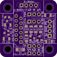
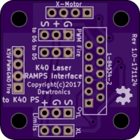
K40 Laser RAMPS Interface
author: dewhisna
2 layer board of 1.19 x 1.19 inches (30.2 x 30.2 mm)
Uploaded:
November 26, 2017
Shared:
November 26, 2017
Total Price:
$7.05
This is a K40 40W CO2 (Chinese) Laser to RAMPS Interface board. Similar to the “K40 Middle Man” board, but is more of a “K40 Middle Woman” – that is, it was created second and is more complicated, er uh, I mean more sophisticated.
Unlike the Middle Man board, this board drops all water pump and 12V routing signals, since it wasn’t relevant to my configuration. What it adds is (hopefully) better interface circuitry between the RAMPS and the K40 Laser Power Supply. The PCB footprint, however, was kept the same as the K40 Middle Man to be a physical drop-in replacement. Parts of this circuit was derived from the M2Nano control board on my laser and from its documentation from http://www.3wcad.com, including corrections to the commonly listed pin-out of the 12-pin ribbon cable connector, which generally is missing a second ground pin and a secondary YL (Y-limit) switch pin.
Interface Circuitry added over the basic trace routing is as follows:
1) Current limiting and voltage clamping on the X and Y axis limit switch inputs has been added. This is useful in case there’s a short in the ribbon cable between the endstop lines and the motor control lines. It would be better to fry a resistor or diode in this circuit than your entire control board stack.
2) A Laser Fire signal buffer has been added that filters it for noise, both with a simple low-pass filter and with a transistor circuit that requires a current flow instead of just a voltage change. It also uses the K40’s +5V line as its pull-up, allowing you to drop power to your RAMPS board (and its processors) and not accidentally fire the laser. This change does, however, require that you define “HIGH_TO_FIRE” in the Configuration.h file of your firmware when you compile it, as this circuit needs a high-signal to fire the laser.
3) A low-pass filter has been added to the Laser PWM output signal to make it more of a proper DAC signal to operate in place of the potentiometer on the K40 design. Presumably, the K40 laser’s power supply already has some filtering circuitry since others are getting away without using a filter, but this addition should help.
Any or all parts of the circuit changes are easily bypassed by omitting parts and/or adding 0-ohm jumper “resistors” in their place to get a simple “pass-through” board like the “K40 Middle Man”.
All surface mount resistors and capacitors are 1206 footprint. The schematic and bill-of-materials will be made available on GitHub, and linked here, once the circuit has been fully proven (i.e. once I finish my K40 Laser build).

