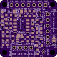
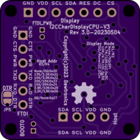
I2C Character Display CPU V3
author: dewhisna
2 layer board of 1.00 x 1.00 inches (25.4 x 25.4 mm)
Uploaded:
June 13, 2023
Shared:
June 13, 2023
Total Price:
$5.00
ERRATA: While not technically a problem with the PCB, the STM32G050F6Px processor that was intended to be used on this board doesn’t have nearly enough flash space for the code required to implement the desired display functionality. However, there’s a drop-in replacement with the STM32G051F8Px, which doubles the flash size from 32K to 64K, which is sufficient. Therefore, when building this board, use the STM32G051F8Px instead. Note the “8” in the part number. That’s the important number that means 64K instead of 32K. Note that it’s also a change in the processor family from the G050 to the G051, since the G050 family doesn’t have a F8 variant.
V3 Update to the I2C Character Display CPU V2 Board. This board goes inline between a host CPU and an OLED (or similar) I2C/SPI graphical display. Its purpose is to convert the graphical display into a character-based display, removing the overhead of font rendering and pixel transfer over the slow I2C bus from the host.
This version is an overall enhancement, using the STM32G050F6P6 STM32G051F8P6 MCU instead of the ATmega328PB. The new processor gives much more computing power for better graphics frame buffers (having 18K of RAM instead of only 2K) and a higher (up to 64MHz) processing speed. It’s also better suited for working with both 5V and 3.3V displays and host systems.
Like the V2 board, it also supports interfacing with the display using either I2C or SPI. But unlike the V1 and V2 boards, there’s no need for a board with a reversed connector. The V1 and V2 boards required that because the ISP port on those versions was a dual-row connection and so couldn’t be mounted on the reverse side. This board only has single-row connections and so the pinout is identical whether the header connectors are mounted on the top or bottom.
For ISP programming of this board, there are two options. You can use either the USART FTDI compatible port or the Host I2C connection and enable the STM32 boot loader via the BOOT0 jumper. If you have an adapter to program via the I2C port, you can elect to not populate the USART/FTDI connector and associated level-shifting logic components unless you want that port for debugging or other serial communications purposes.
This board is designed to work with either 3.3V or 5V displays. For 3.3V displays, skip populating the on-board voltage regulator and bridge the solder-jumper integrated into its footprint. You do, however, have to supply 3.3V power on the Host I2C and this board becomes a “3.3V display device”. For 5V displays, supply 5V on the Host I2C and populate the voltage regulator.
Important: This processor doesn’t enable the external BOOT0 pin by default. Therefore, in your firmware, be sure to either enable the BOOT0 pin during the very first programming via the bootloader over the FTDI link, or make sure your firmware enables the bootloader in some fashion, or you will not be able to program the processor a second time without manually patching onto the SWD pins.
One neat programming mechanism is for the firmware to simply set the EMPTY flag in `FLASH->ACR during initial setup. That will allow any reset that isn’t a POR or OBL_LAUNCH reset (i.e. a reset that doesn’t reload the boot option bytes) to run the bootloader instead. Using this mechanism and with the DTR jumper in place on the FTDI port, you can have stm32flash, via the -i option, toggle the DTR line and automatically reset this board and put it in the bootloader without needing to install the BOOT0 or worry about the option bytes at all. Or, you can even do both, so that there’s a fallback.

