MX-P50M Keyer Mod
author: SyncChannelBlog
2 layer board of 0.50 x 0.25 inches (12.7 x 6.4 mm)
Uploaded:
June 01, 2022
Shared:
June 02, 2022
Total Price:
$0.60
Tiny PCB (0.5"x0.25") for modifying the MX-P50M HF amplifier with an upgraded keyer circuit. The circuit is added in-line on the keying wire to buffer the signal from the radio and add a flyback diode across the transmit relay, greatly improving safety for the radio itself.
This mod was created by Kevin Loughin KB9RLW, please see his excellent YouTube video here where he describes the circuit, the theory of operation and the justification for adding it to the amp: Ham Radio - Modifying the MX-P50M amplifier to fix keying and installing it to my desk.. All credit goes to him for the original mod. You should also check out this video by Mike K8MRD where he demonstrates performing the mod on his own amp and installing the circuit: MX-P50M Keyer Mod and Installation for Icom 705. While it’s very possible to build the circuit with through-hole components as shown in both videos, I decided to make a small PCB with surface mount components to create a cleaner finished product for the mod.
Parts List:
- Q1: MMST5401-7-F PNP Transistor SOT323 (Digikey)
- D1: 1N4148 Diode SOD123 (Digikey)
- R1: 10k 0805 Resistor (Digikey)
Assembly:
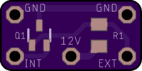
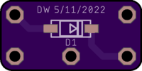
Assembly of this board is straightforward if you are comfortable soldering very small SMD components. All three components on the PCB have different footprints, so there is little risk of installing a part in the wrong spot. Please do watch the polarity of the diode. The stripe on the body of the diode lines up with the stripe on the PCB.
Testing the Board:
It is possible to test your assembled board after soldering the components and before installing it inside of your amplifier. You will need an LED and a resistor of about 1k ohm. Through hole components are fine and a breadboard would help with this to quickly assemble the test circuit and provide a place to connect your hookup wires. I personally connected the LED and resistor on a breadboard along with the supply voltage, used jumper wires coming off of the breadboard and just jammed them into the holes of the PCB and held everything together with my fingers for the few seconds it took to conduct the test.
- Connect the Anode (positive) side of the LED to some supply voltage, anything from 5-15V is fine. You could use a 9V battery, 12V from a radio battery, etc.
- Connect the Cathode (negative) side of the LED to one end of the resistor, and connect the other end of the resistor to the INT hole on the mod PCB.
- Connect the same supply voltage you used on the LED to the 12V hole on the mod PCB, and also connect one of the GND holes on the PCB to the ground of the supply.
- At this point the mod circuit is active and the LED should be OFF.
- Connect a wire to the EXT hole on the mod PCB and touch it to the ground of the supply. The LED should turn ON. As soon as you remove the wire from ground, the LED should turn back OFF. This replicates the SEND line from the radio dropping low during transmit.
That’s it. Use an LED with a current limiting resistor as a load hooked up to the emitter of the PNP transistor, and ensure that the transistor turns on when the base is pulled to ground to sink current through the LED.
Install Photos:
The board is designed to be easily inserted in-line on the keying wire inside of the MX-P50M amplifier. The PCB is shown here assembled with the SMD components that implement the mod circuit in KB9RLW’s video.

Cut the keying wires (smaller red and black wires) inside of the amplifier approximately half way between the case and the white connector that goes to the amp internally. Strip a small amount of insulation off the ends of each wire. As you see here, the mod PCB is designed with holes on the corners for the four wire ends that you just prepped. The side of the red wire that goes to the outside of the amp and the radio is soldered to EXT, the side of the red wire that goes to the PCB of the amplifier is soldered to INT, and the two ends of the black ground wire are soldered to the GND holes.

Here the board is soldered to the red and black keying wires. I decided to insert the wires into the holes from the underside to create a neater final install that would sit nicely inside of the amplifier.

Next solder a small gauge wire to the 12V hole on the mod PCB. Eight inches of 16 gauge wire or so should work. I once again inserted the wire from the underside of the board as shown. Once this wire is soldered, you can clean the flux residue off of the mod PCB if you desire with some flux cleaner or isopropyl alcohol.

Now you should apply some heat shrink over the mod PCB to seal things up and help to prevent shorts. 3/8" 3:1 heat shrink worked for me. With that applied, you can reconnect the white connector on the keying wire to the circuit board of the amp and start to tuck the mod circuit down into the case of the amplifier behind the relays.

Finally, solder the 12V wire from the mod circuit to the amplifier board on the same pad where the main incoming supply (larger red wire) goes. Tiddy things up inside of the case, re-install the bottom cover and test the amplifier.

This mod works great in my amplifier, and I’m happy to know that the mod circuit is just as robust and reliable as the rest of the circuitry inside of the amp. Good luck with the mod if you decide to try it yourself.
Tiny PCB (0.5"x0.25") for modifying the MX-P50M HF amplifier with an upgraded keyer circuit. The circuit is added in-line on the keying wire to buffer the signal from the radio and add a flyback diode across the transmit relay, greatly improving safety for the radio itself.
This mod was created by Kevin Loughin KB9RLW, please see his excellent YouTube video here where he describes the circuit, the theory of operation and the justification for adding it to the amp: Ham Radio - Modifying the MX-P50M amplifier to fix keying and installing it to my desk.. All credit goes to him for the original mod. You should also check out this video by Mike K8MRD where he demonstrates performing the mod on his own amp and installing the circuit: MX-P50M Keyer Mod and Installation for Icom 705. While it’s very possible to build the circuit with through-hole components as shown in both videos, I decided to make a small PCB with surface mount components to create a cleaner finished product for the mod.
Parts List:
- Q1: MMST5401-7-F PNP Transistor SOT323 (Digikey)
- D1: 1N4148 Diode SOD123 (Digikey)
- R1: 10k 0805 Resistor (Digikey)
Assembly:
Assembly of this board is straightforward if you are comfortable soldering very small SMD components. All three components on the PCB have different footprints, so there is little risk of installing a part in the wrong spot. Please do watch the polarity of the diode. The stripe on the body of the diode lines up with the stripe on the PCB.
Testing the Board:
It is possible to test your assembled board after soldering the components and before installing it inside of your amplifier. You will need an LED and a resistor of about 1k ohm. Through hole components are fine and a breadboard would help with this to quickly assemble the test circuit and provide a place to connect your hookup wires. I personally connected the LED and resistor on a breadboard along with the supply voltage, used jumper wires coming off of the breadboard and just jammed them into the holes of the PCB and held everything together with my fingers for the few seconds it took to conduct the test.
- Connect the Anode (positive) side of the LED to some supply voltage, anything from 5-15V is fine. You could use a 9V battery, 12V from a radio battery, etc.
- Connect the Cathode (negative) side of the LED to one end of the resistor, and connect the other end of the resistor to the INT hole on the mod PCB.
- Connect the same supply voltage you used on the LED to the 12V hole on the mod PCB, and also connect one of the GND holes on the PCB to the ground of the supply.
- At this point the mod circuit is active and the LED should be OFF.
- Connect a wire to the EXT hole on the mod PCB and touch it to the ground of the supply. The LED should turn ON. As soon as you remove the wire from ground, the LED should turn back OFF. This replicates the SEND line from the radio dropping low during transmit.
That’s it. Use an LED with a current limiting resistor as a load hooked up to the emitter of the PNP transistor, and ensure that the transistor turns on when the base is pulled to ground to sink current through the LED.
Install Photos:
The board is designed to be easily inserted in-line on the keying wire inside of the MX-P50M amplifier. The PCB is shown here assembled with the SMD components that implement the mod circuit in KB9RLW’s video.

Cut the keying wires (smaller red and black wires) inside of the amplifier approximately half way between the case and the white connector that goes to the amp internally. Strip a small amount of insulation off the ends of each wire. As you see here, the mod PCB is designed with holes on the corners for the four wire ends that you just prepped. The side of the red wire that goes to the outside of the amp and the radio is soldered to EXT, the side of the red wire that goes to the PCB of the amplifier is soldered to INT, and the two ends of the black ground wire are soldered to the GND holes.

Here the board is soldered to the red and black keying wires. I decided to insert the wires into the holes from the underside to create a neater final install that would sit nicely inside of the amplifier.

Next solder a small gauge wire to the 12V hole on the mod PCB. Eight inches of 16 gauge wire or so should work. I once again inserted the wire from the underside of the board as shown. Once this wire is soldered, you can clean the flux residue off of the mod PCB if you desire with some flux cleaner or isopropyl alcohol.

Now you should apply some heat shrink over the mod PCB to seal things up and help to prevent shorts. 3/8" 3:1 heat shrink worked for me. With that applied, you can reconnect the white connector on the keying wire to the circuit board of the amp and start to tuck the mod circuit down into the case of the amplifier behind the relays.

Finally, solder the 12V wire from the mod circuit to the amplifier board on the same pad where the main incoming supply (larger red wire) goes. Tiddy things up inside of the case, re-install the bottom cover and test the amplifier.

This mod works great in my amplifier, and I’m happy to know that the mod circuit is just as robust and reliable as the rest of the circuitry inside of the amp. Good luck with the mod if you decide to try it yourself.

