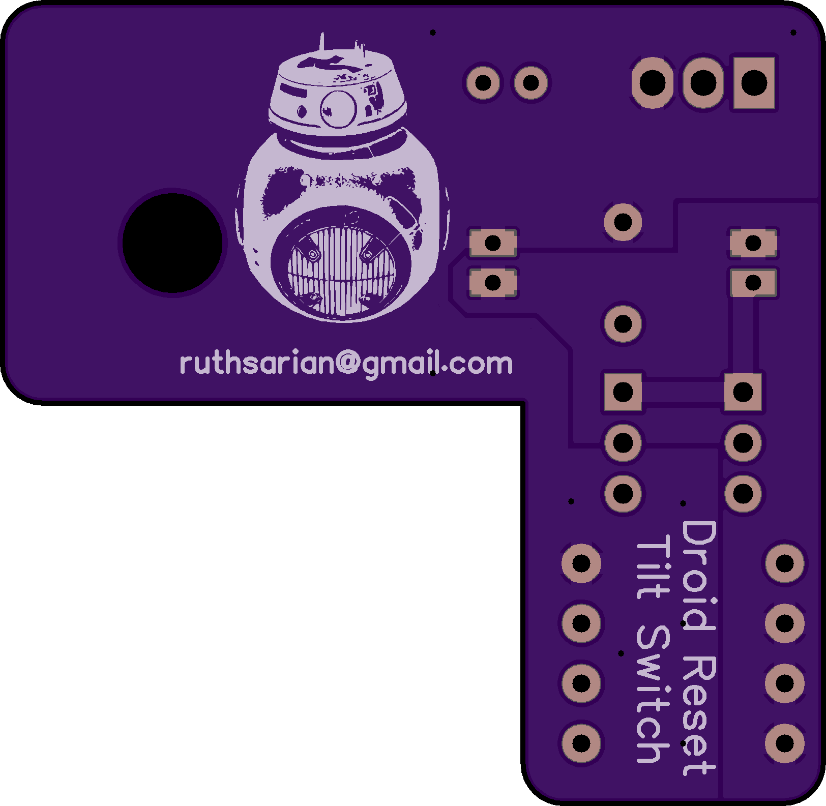
BB Droid Reset Tilt Switch
author: ruthsarian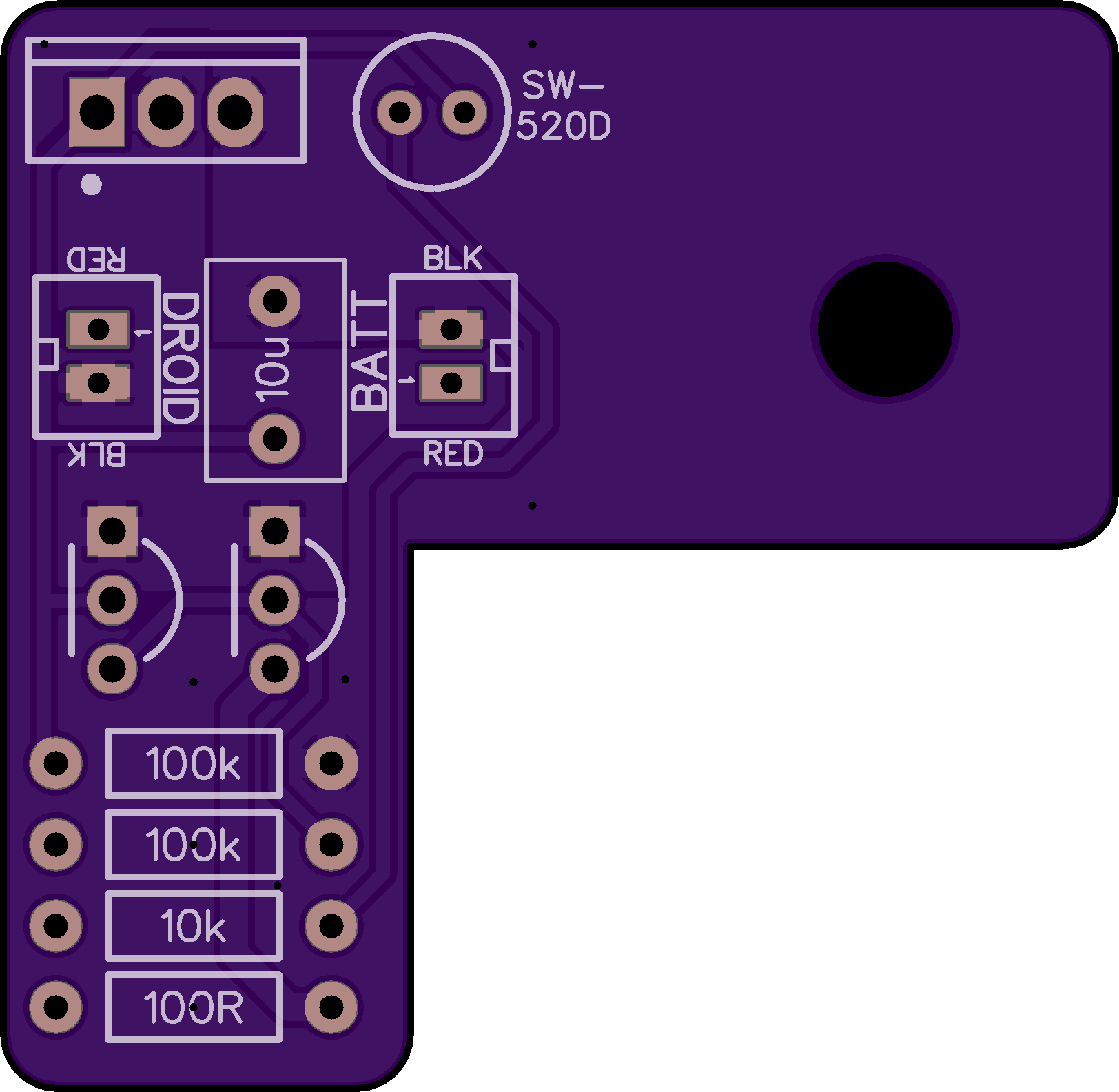
2 layer board of 1.62 x 1.58 inches (41.1 x 40.1 mm)
Uploaded:
September 26, 2025
Shared:
September 26, 2025
Total Price:
$12.75
See this project for a universal, surface mount version.
Note: I recommend ordering this PCB with the 2oz copper, 0.8mm option.
This circuit provides a means to cycle the power on a Galaxy’s Edge droid (especially BB-units) to wake them up after they go to sleep (from 5 minutes of inactivity) by briefly tilting the droid upside down.
This PCB is designed specifically for BB units to fit over a nub on the outside of the plastic housing of the BB’s motor, specifically the motor to the right of the logic PCB. This pcb would be placed with the component silk screen facing in towards the logic PCB and the droid silkscreen side facing away.
This design uses only through-hole components to make soldering a little easier.
The power transistor should be a logic-level N-channel MOSFET in a TO-220 package. Something like an IRLZ44N will work, but there are many options out there.
When soldered to the board, the MOSFET should stick out horizontally, do not bend it to face as it will not fit when the BB unit is closed.
The tilt switch should be bent away from the PCB, but parallel with the PCB, such that when the BB is upright it is making a connection.
The connectors used are JST-PH 2.0mm pitch connectors. I suggest a female socket for the BATT connector and a cable with a male connector for the DROID connector. This will allow you to plug the battery connector into the PCB and then connect the PCB to the battery connector on the logic PCB.
Note: links in BOM below are not affiliate links, just examples of where you could possibly locate the components needed to assemble this PCB if you do not already have them.
BOM:
- 2 x 100k 1/4W through-hole resistor
- 1 x 10k 1/4W through-hole resistor
- 1 x 100 ohm 1/4W through-hole resistor (this has all necessary resistors)
- 2 x 2n7000 N-Channel MOSFET in TO-92 package
- 1 x 10uF ceramic capacitor (this set includes 10uF capacitors)
- 1 x JST-PH 2.0mm female socket
- 1 x JST-PH 2.0mm male lead (this has both connectors)
- 1 x SW-520D tilt switch
- 1 x IRLZ44N N-Channel MOSFET in TO-220 package
