ATX PSU Latching Circuit for Mom Switch - Rev.C
author: ziggy587
2 layer board of 0.99 x 1.00 inches (25.1 x 25.4 mm)
Uploaded:
July 28, 2024
Shared:
August 16, 2024
Total Price:
$4.90
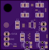
This is a simple circuit that will turn on an ATX power supply using a momentary switch. I made this specifically to use an AT style motherboard in an ATX case, however, you could use this generically in any case that you want to turn an ATX PSU on/off using a momentary switch.
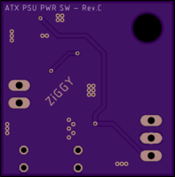
The mounting hole is sized to fit a 6-32 screw so that you can mount the board using a standard motherboard standoff.
I’m using one of those common AT-to-ATX power adapters, which already breaks out the COM and PS_ON wires. If using one of these adapters, you will most likely have to add a pin/wire for the +5VSB signal.
This is an updated version of the PCB found here: https://oshpark.com/shared_projects/h6LgDD3k
I have added LED status lights. LED1 is to indicate standby, and will light when there’s a +5VSB signal. LED2 is to indicate that the PSU has been turned on, and will light when you press the switch and the circuit pulls PS_ON low.
This has been bench tested and found to work as intended. It has also been used with a baby AT motherboard and ATX power supply for several hours and found to work as intended. However, as always, use at your own risk.
The latching circuit was taken from a post found on Stack Exchange. More info can be found here: https://electronics.stackexchange.com/questions/186841/momentary-button-as-switch
- U1 - 74LVC2G04 (SOT-23-6)
- R1 - 1 k ohm (0805)
- R2 - 100 k ohm (0805)
- R3 - 10 k ohm (0805)
- C1 - 100 nF (0805)
- C2 - 10 nF (0805)
R4 and R5 are both 0805, be sure to chose values that respect that max current output of the 74LVC2G04.
LED1 and LED2 have pads for 3mm through hole or 0805 surface mount parts. Use either surface mount or through hole, not both. The through hole LED footprints are for 3mm, but 5mm will also fit. You can simply omit R4, R5 and the LEDs if you do not wish to use them.
There is a mistake with the LED silkscreen, the line to indicate the flat side of the LED bulb is on the wrong side. When placing the LED, be sure to place the flat side or cathode side opposite of the silkscreen line.
Use standard 2.54mm single row pin headers for PWR_SW, this is what an ATX style computer case will use for its power switch.
You can also use 2.54mm pin headers for the +5VSB, COM and PS_ON signals, but I found it to be annoying due to the weight of those wires. I ended up using a 3-pin JST-XH connector here, they are also 2.54mm but more secure since they snap it.
I consider this version to be deprecated, but will leave it up in case anyone needs it. An updated version can be found here: https://oshpark.com/shared_projects/f07pnuO2

