GBC USB-C JACK V1F
author: GG_CUSTOMS_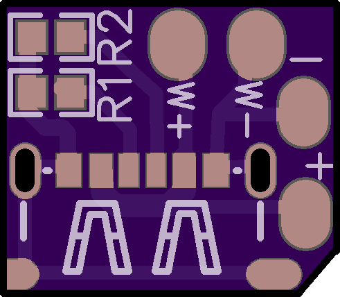
2 layer board of 0.48 x 0.42 inches (12.3 x 10.7 mm)
Uploaded:
February 23, 2022
Shared:
December 07, 2022
Total Price:
$1.00
This is a USB type C jack that I specifically designed for the Gameboy Color to wire to a lipo charging module. You need to solder it directly to the motherboard and replacing the DC jack connector, allowing you to have a better look on your build and get more room on the battery compartment. Can be charged with any USB-C charger safely, the jack board has a circuit that only provides 5v max input.
Instructions: USB-C BOARD. 1.- Solder 5.1k ohm resistors 0603 size to R1 and R2. 2.- Place and solder a USB-C 6 pin female jack to the board, you can bend the front anker pins so they can fit on the board or trim those ones. The USB-C port that you need should look like this one: https://aliexpress.com/item/4001054493231.html?spm=a2g0o.productlist.0.0.61233a56aRLM7o&algo_pvid=11ce47ef-8b4e-459f-82dd-ff9aaf936088&aem_p4p_detail=202111082245423538519152746340044004769&algo_exp_id=11ce47ef-8b4e-459f-82dd-ff9aaf936088-7&pdp_ext_f=%7B%22sku_id%22%3A%2210000013821822616%22%7D
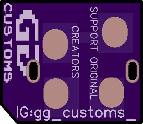
GAMEBOY COLOR MOTHERBOARD. 1.- Remove the DC input connector from the motherboard. 2.- Clean the pads. 3.- Place the USB-C JACK BOARD to the Gameboy motherboard and solder the pads on the bottom of the board correctly. If you don’t solder the bottom pads to the Gameboy mother board the Gameboy WONT WORK. 4.- Solder the pads on the top of the board to the corresponding Positive (+) and negative (-) pads of your lipo charging module. 5.- Enjoy. OPTIONAL. You can also add wireless charging module to all the circuit, you just need to solder the positive and negative wires to the ones on top of the USB-C JACK board that are marked as “W+” and “W-“. You can order it with 1.6mm thickness or 0.8mm.
If you have any questions, feel free to contact me on: https://linktr.ee/gg_customs_
This is a USB type C jack that I specifically designed for the Gameboy Color to wire to a lipo charging module. You need to solder it directly to the motherboard and replacing the DC jack connector, allowing you to have a better look on your build and get more room on the battery compartment. Can be charged with any USB-C charger safely, the jack board has a circuit that only provides 5v max input.
Instructions: USB-C BOARD. 1.- Solder 5.1k ohm resistors 0603 size to R1 and R2. 2.- Place and solder a USB-C 6 pin female jack to the board, you can bend the front anker pins so they can fit on the board or trim those ones. The USB-C port that you need should look like this one: https://aliexpress.com/item/4001054493231.html?spm=a2g0o.productlist.0.0.61233a56aRLM7o&algo_pvid=11ce47ef-8b4e-459f-82dd-ff9aaf936088&aem_p4p_detail=202111082245423538519152746340044004769&algo_exp_id=11ce47ef-8b4e-459f-82dd-ff9aaf936088-7&pdp_ext_f=%7B%22sku_id%22%3A%2210000013821822616%22%7D
GAMEBOY COLOR MOTHERBOARD. 1.- Remove the DC input connector from the motherboard. 2.- Clean the pads. 3.- Place the USB-C JACK BOARD to the Gameboy motherboard and solder the pads on the bottom of the board correctly. If you don’t solder the bottom pads to the Gameboy mother board the Gameboy WONT WORK. 4.- Solder the pads on the top of the board to the corresponding Positive (+) and negative (-) pads of your lipo charging module. 5.- Enjoy. OPTIONAL. You can also add wireless charging module to all the circuit, you just need to solder the positive and negative wires to the ones on top of the USB-C JACK board that are marked as “W+” and “W-“. You can order it with 1.6mm thickness or 0.8mm.
If you have any questions, feel free to contact me on: https://linktr.ee/gg_customs_
