LFAmp - Low Frequency (Audio) Amplifier
author: BattleToad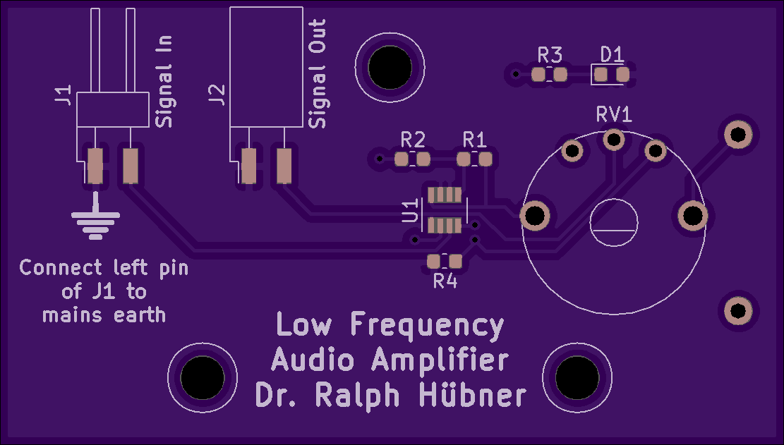
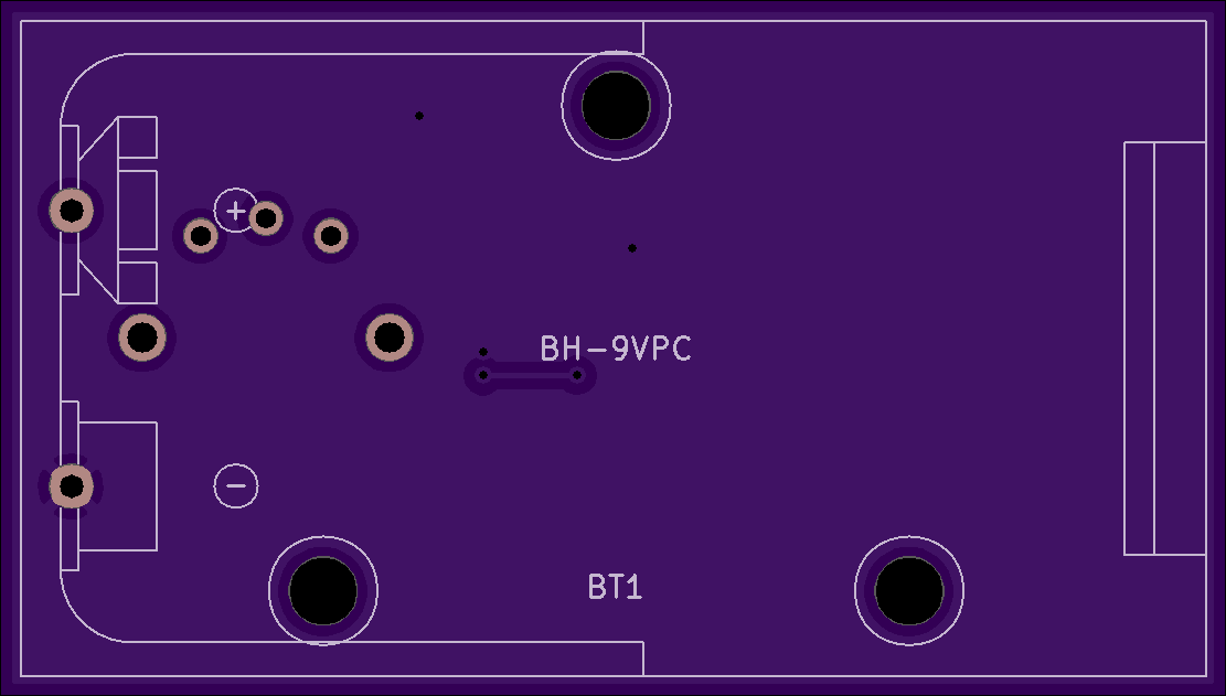
2 layer board of 2.22 x 1.26 inches (56.4 x 32.0 mm)
Uploaded:
February 05, 2020
Shared:
February 05, 2020
Total Price:
$14.00
BOM
Contact me if there are questions.
The reason for this Project was the tiny output of my old detector radios which had to be substantially enhanced.
To keep it simple I just wanted to use an opamp to increase the volume by a factor of say 100. Audio signals, however, carry positive and negative voltage levels which means that the opamp had to be provided with both a positive and a negative power rail. I don’t like having two batteries in my design and so I had to find a way to correlate the 0V level of the audio signal to the midst of the available battery voltage.
It is easy to use a voltage divider to generate that mid voltage. However, you can’t tap any power from it without having the tapped voltage wander off because the load circuit changes the resistance ratio of the voltage divider. This means that somehow the tapped voltage has to be stabilized. One way to achieve this is an additional opamp which acts as a buffer, which is why a dual opamp would come in handy. The Analog Devices AD8034 is rail-to-rail and has more than enough of a voltage range.
The PCB offers enough real estate to use 0805 parts and a SOIC-8 chip. I went for 0603 parts and a SOT-23-8 chip instead because there are so few components on this board that its assembly serves as a nice study in soldering smaller structures.
Schematics:

3D Model:

BOM
Contact me if there are questions.
The reason for this Project was the tiny output of my old detector radios which had to be substantially enhanced.
To keep it simple I just wanted to use an opamp to increase the volume by a factor of say 100. Audio signals, however, carry positive and negative voltage levels which means that the opamp had to be provided with both a positive and a negative power rail. I don’t like having two batteries in my design and so I had to find a way to correlate the 0V level of the audio signal to the midst of the available battery voltage.
It is easy to use a voltage divider to generate that mid voltage. However, you can’t tap any power from it without having the tapped voltage wander off because the load circuit changes the resistance ratio of the voltage divider. This means that somehow the tapped voltage has to be stabilized. One way to achieve this is an additional opamp which acts as a buffer, which is why a dual opamp would come in handy. The Analog Devices AD8034 is rail-to-rail and has more than enough of a voltage range.
The PCB offers enough real estate to use 0805 parts and a SOIC-8 chip. I went for 0603 parts and a SOT-23-8 chip instead because there are so few components on this board that its assembly serves as a nice study in soldering smaller structures.
Schematics:
3D Model:
