Shared Projects by BattleToad
Shared Projects by BattleToad
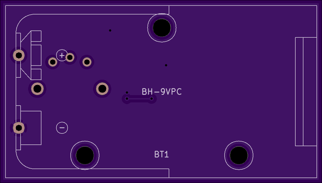
Balanced <=> Unbalanced Audio Conversion
2 layer board of 5.08 x 1.97 inches (129.0 x 50.0 mm)
Uploaded:
April 18, 2025
Shared:
April 18, 2025
Total Price:
$49.95
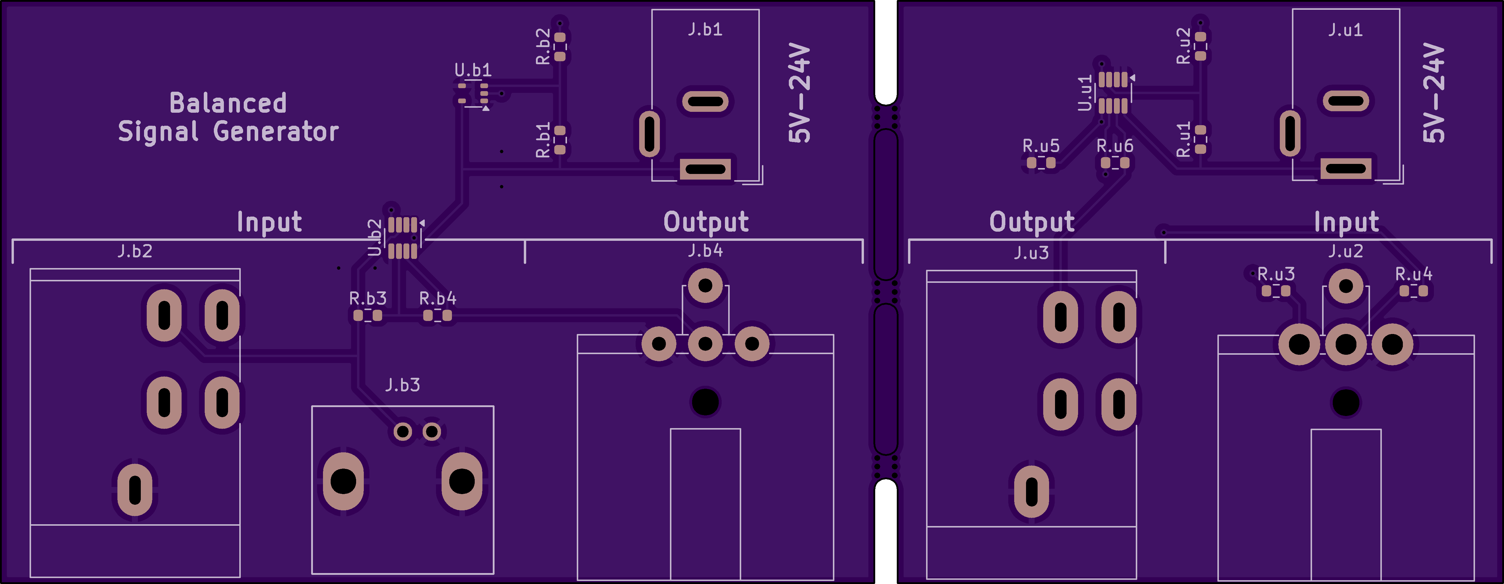
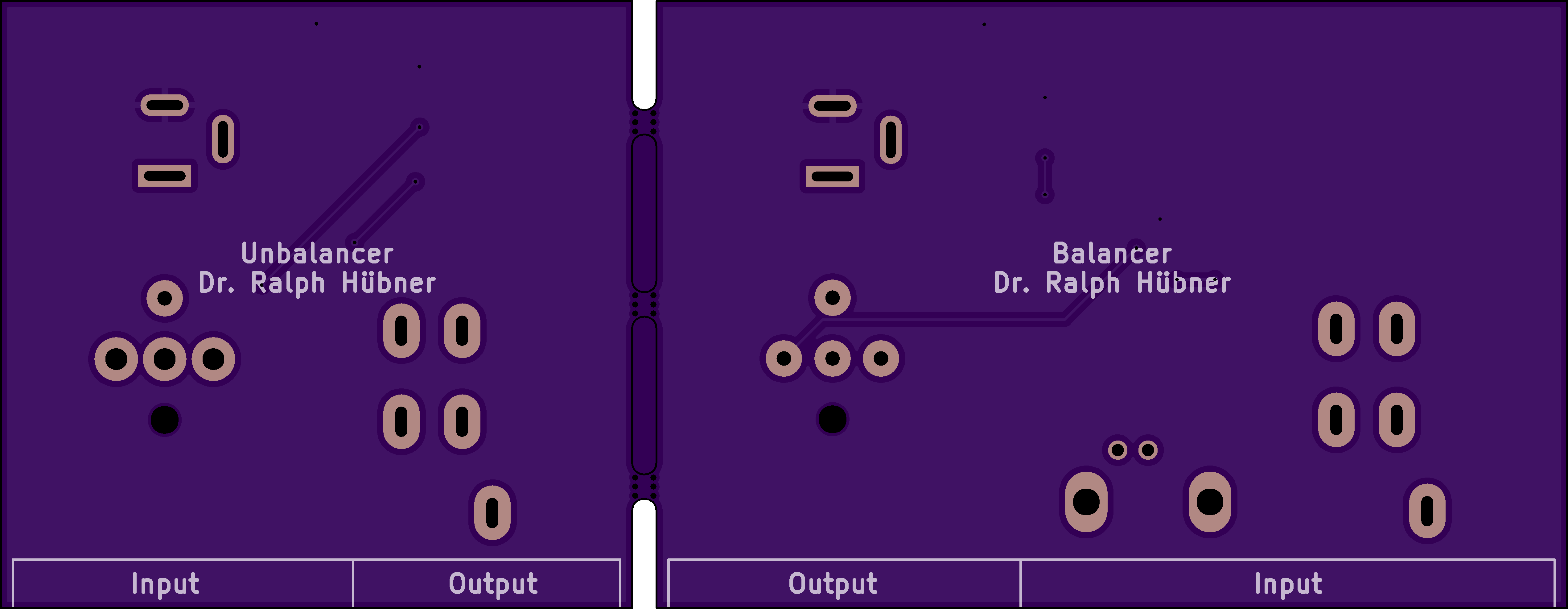
A pair of boards ("Balancer" and "Unbalancer") which convert unbalanced and balanced audio signals back and forth.
BOM
[Contact](mailto:[email protected]?subject=Feedback…
A pair of boards (“Balancer” and “Unbalancer”) which convert unbalanced and balanced audio signals back and forth.
BOM
Contact me if there are questions.
One application would be a frontend to a function generator which itself is single ended. Together with the “Balancer” board, that function generator would give a balanced output. When equipped with AD8033 and AD8034 OpAmps from Anolog Devices, the boards can be driven with 5V - 24V (center pin positive), so line level audio signals are easily produced.
The boards have the following input and output terminals:
- A common BNC connector
- Balanced XLR panel mount receptacles from the Neutrik D series, NC3MD-H (male) and NC3FD-H (female)
- Unbalanced TS mono jacks from Marshall, MESKTP00005
Schematics:

3D Model:

Show full description
A pair of boards ("Balancer" and "Unbalancer") which convert unbalanced and balanced audio signals back and forth.
BOM
[Contact](mailto:[email protected]?subject=Feedback…
A pair of boards (“Balancer” and “Unbalancer”) which convert unbalanced and balanced audio signals back and forth.
BOM
Contact me if there are questions.
One application would be a frontend to a function generator which itself is single ended. Together with the “Balancer” board, that function generator would give a balanced output. When equipped with AD8033 and AD8034 OpAmps from Anolog Devices, the boards can be driven with 5V - 24V (center pin positive), so line level audio signals are easily produced.
The boards have the following input and output terminals:
- A common BNC connector
- Balanced XLR panel mount receptacles from the Neutrik D series, NC3MD-H (male) and NC3FD-H (female)
- Unbalanced TS mono jacks from Marshall, MESKTP00005
Schematics:
3D Model:
Show full description
-
Actions
- Order Board
- Download
- Permalink
- Embed link
Ordering shared project
Hey there! Before ordering, make sure you have all the info you need to complete and use this design. This usually means a component list, and sometimes additional information such as assembly notes, source code, or usage guides.Since this is a project designed by a community member, it may contain design errors that prevent it from working as intended. OSH Park cannot place any guarantees about the functionality or correctness of the design.
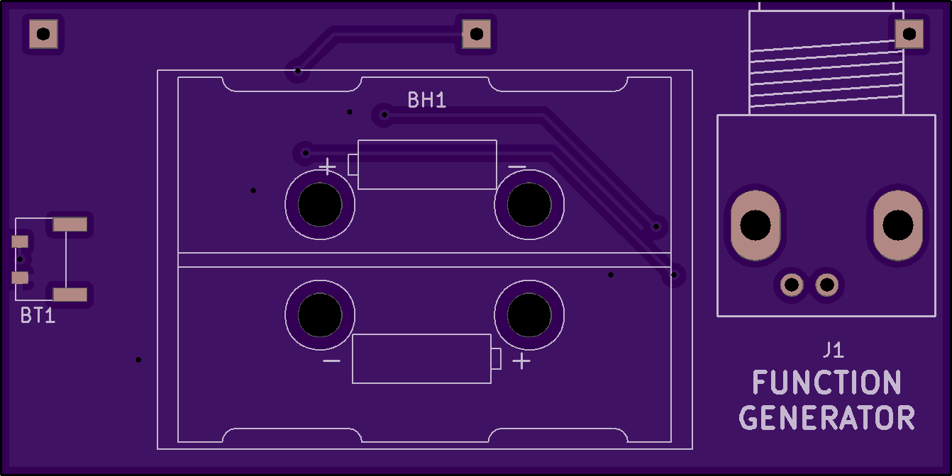
TXAnAmp - TX Antenna Amplifier

2 layer board of 2.57 x 1.70 inches (65.2 x 43.2 mm)
Uploaded:
April 06, 2021
Shared:
May 22, 2021
Total Price:
$21.75
BOM
Contact me if there are questions.
About a year ago, I have built a small AM radio transmitter ([project AMTrans](https://oshp…
BOM
Contact me if there are questions.
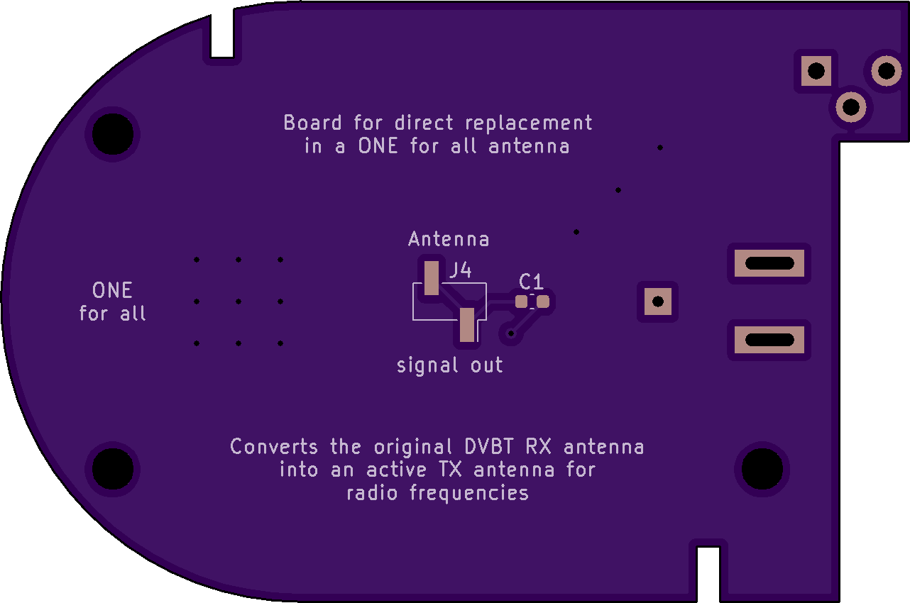
About a year ago, I have built a small AM radio transmitter (project AMTrans) which was supposed to boadcast audio content over a short range. Although this transmitter does work in principle, its range leaves much to be desired. My idea was to combine this transmitter with a leftover DVBT antenna which I wanted to convert into an active transmission antenna for radio signals.
Unfortunately, I am not exactly an expert in high frequency electronics which is almost voodoo to me. My approach is naively relying on common sense combined with a healthy touch of “bigger is better” :-). The design is based on the dual opamp approach which I have used before e.g. in my curve tracer project. One opamp buffers the central tap of a voltage divider which establishes the positive and negative rail for the second opamp, the one which does the actual amplification.
It turned out that this amplifier circuit interfered with my transmitter and saturated its coupling capacitor over time. Resistor R5 lets this accumulating charge trickle off. I got this idea when I remembered the grid leak of ancient vacuum tube based radio technology. A grid leak is a high-ohmic resistor which either bypasses the coupling capacitor of the grid or connects the grid to the cathode. Both ways the grid’s bias is stabilized by draining those electrons which inside the tube are heading for the anode but accidentally hit the grid. Without the grid leak, a negative charge would accumulate on the grid which would negatively affect the functioning of the tube :-).
The original DVBT antenna was driven by a 6V power supply and at first I intended to reuse this. However, my AD8034 opamps are specified for 24V operation, so why not ramp up the output of the antenna a little bit (which is the bigger - is - better part)? So I ordered a linear 24V power supply from AliExpress and used this instead.
Luckily there is room enough in the housing to solder a two-pin connection header onto the antenna lug. This way, the PCB can be just plugged onto this header and screwed down safely like the original board.
After all, this naive approach to amplfy the antenna signal seems to work. I can receive the radio signal inside a room and even in the adjacent ones. Of cause I have to find a spot without noise from all those switching regulators, but neverthless I call this design a success :-).
Schematics:

3D Model:


Show full description
BOM
Contact me if there are questions.
About a year ago, I have built a small AM radio transmitter ([project AMTrans](https://oshp…
BOM
Contact me if there are questions.
About a year ago, I have built a small AM radio transmitter (project AMTrans) which was supposed to boadcast audio content over a short range. Although this transmitter does work in principle, its range leaves much to be desired. My idea was to combine this transmitter with a leftover DVBT antenna which I wanted to convert into an active transmission antenna for radio signals.
Unfortunately, I am not exactly an expert in high frequency electronics which is almost voodoo to me. My approach is naively relying on common sense combined with a healthy touch of “bigger is better” :-). The design is based on the dual opamp approach which I have used before e.g. in my curve tracer project. One opamp buffers the central tap of a voltage divider which establishes the positive and negative rail for the second opamp, the one which does the actual amplification.
It turned out that this amplifier circuit interfered with my transmitter and saturated its coupling capacitor over time. Resistor R5 lets this accumulating charge trickle off. I got this idea when I remembered the grid leak of ancient vacuum tube based radio technology. A grid leak is a high-ohmic resistor which either bypasses the coupling capacitor of the grid or connects the grid to the cathode. Both ways the grid’s bias is stabilized by draining those electrons which inside the tube are heading for the anode but accidentally hit the grid. Without the grid leak, a negative charge would accumulate on the grid which would negatively affect the functioning of the tube :-).
The original DVBT antenna was driven by a 6V power supply and at first I intended to reuse this. However, my AD8034 opamps are specified for 24V operation, so why not ramp up the output of the antenna a little bit (which is the bigger - is - better part)? So I ordered a linear 24V power supply from AliExpress and used this instead.
Luckily there is room enough in the housing to solder a two-pin connection header onto the antenna lug. This way, the PCB can be just plugged onto this header and screwed down safely like the original board.
After all, this naive approach to amplfy the antenna signal seems to work. I can receive the radio signal inside a room and even in the adjacent ones. Of cause I have to find a spot without noise from all those switching regulators, but neverthless I call this design a success :-).
Schematics:
3D Model:
Show full description
-
Actions
- Order Board
- Download
- Permalink
- Embed link
Ordering shared project
Hey there! Before ordering, make sure you have all the info you need to complete and use this design. This usually means a component list, and sometimes additional information such as assembly notes, source code, or usage guides.Since this is a project designed by a community member, it may contain design errors that prevent it from working as intended. OSH Park cannot place any guarantees about the functionality or correctness of the design.
YACT - Yet Another Curve Tracer
2 layer board of 2.68 x 1.35 inches (68.2 x 34.2 mm)
Uploaded:
July 01, 2020
Shared:
July 01, 2020
Total Price:
$18.00
BOM
Contact me if there are questions.
I got the inspiration for this project from the YouTube channel Mr. Carlson's Lab, where i…
BOM
Contact me if there are questions.
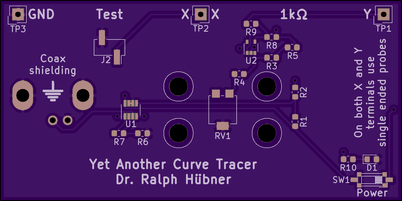
I got the inspiration for this project from the YouTube channel Mr. Carlson’s Lab, where its owner Paul can’t stress enough how useful a curve tracer is for troubleshooting faulty elecrical components. Back in the 1930s and 1940s curve tracers had been integrated into some oscilloscopes from this period. However, nowadays curve tracers are expensive specialized devices like the Huntron Tracker and if you dont feel like spending that kind of money, you have to build your own.
My idea was to make use of the built-in Function Generator which your oscilloscope might already have in order to inject AC current into the component under test. This way I developed an “Octopus”-like frontend for a FG which Dave Jones reviewed in his Mailbag Monday video EEVblog #1137. Octopus circuits are a very simple type of curve tracers which can be easily found on the internet, but as it is shown in the Mailbag video this design only works in combination with an expensive differential probe. In my lengthier project description I talk about this in more depth.
Paul Carlson has published his own version of a curve tracer circuit on Patreon from which I “borrowed” the use of another opamp as a difference amplifier. I added this to my Octopus design and gave this improved version the name YACT. In hindsight, the addition of a difference amplifier which eliminates the need for a differential probe seems like a natural and easy approach. However, a few years ago when I first pondered about the Octopus frontend idea this was somewhat over my head. Regarding to electronics I still am an amateur who needs to gain experience and an effective stimulus (thanks, Paul :-)).
Schematics:

3D Model:


Show full description
BOM
Contact me if there are questions.
I got the inspiration for this project from the YouTube channel Mr. Carlson's Lab, where i…
BOM
Contact me if there are questions.
I got the inspiration for this project from the YouTube channel Mr. Carlson’s Lab, where its owner Paul can’t stress enough how useful a curve tracer is for troubleshooting faulty elecrical components. Back in the 1930s and 1940s curve tracers had been integrated into some oscilloscopes from this period. However, nowadays curve tracers are expensive specialized devices like the Huntron Tracker and if you dont feel like spending that kind of money, you have to build your own.
My idea was to make use of the built-in Function Generator which your oscilloscope might already have in order to inject AC current into the component under test. This way I developed an “Octopus”-like frontend for a FG which Dave Jones reviewed in his Mailbag Monday video EEVblog #1137. Octopus circuits are a very simple type of curve tracers which can be easily found on the internet, but as it is shown in the Mailbag video this design only works in combination with an expensive differential probe. In my lengthier project description I talk about this in more depth.
Paul Carlson has published his own version of a curve tracer circuit on Patreon from which I “borrowed” the use of another opamp as a difference amplifier. I added this to my Octopus design and gave this improved version the name YACT. In hindsight, the addition of a difference amplifier which eliminates the need for a differential probe seems like a natural and easy approach. However, a few years ago when I first pondered about the Octopus frontend idea this was somewhat over my head. Regarding to electronics I still am an amateur who needs to gain experience and an effective stimulus (thanks, Paul :-)).
Schematics:
3D Model:
Show full description
-
Actions
- Order Board
- Download
- Permalink
- Embed link
Ordering shared project
Hey there! Before ordering, make sure you have all the info you need to complete and use this design. This usually means a component list, and sometimes additional information such as assembly notes, source code, or usage guides.Since this is a project designed by a community member, it may contain design errors that prevent it from working as intended. OSH Park cannot place any guarantees about the functionality or correctness of the design.
AMTrans - A most simplistic AM radio transmitter
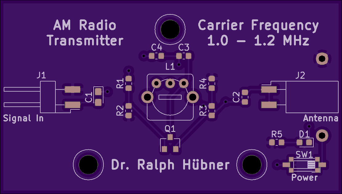
2 layer board of 2.22 x 1.26 inches (56.4 x 32.0 mm)
Uploaded:
March 29, 2020
Shared:
May 29, 2020
Total Price:
$14.00
BOM
Contact me if there are questions.
Recently, when I started playing around with detector radios from the Twenties, I painfu…
BOM
Contact me if there are questions.
Recently, when I started playing around with detector radios from the Twenties, I painfully realized one thing: There are hardly any stations to listen to - at least that’s the case here in Germany where I live. Instead of waiting till after midnight for catching an oddball station under lucky conditions, I rather wanted to broadcast some audio content from my mp3 player or cellphone on a short ranged AM radio transmitter.
Browsing the web I found this website which describes a simple transmitter kit that operates on the medium wave band. The underlying principles of this circuit are not explained here. The AMTrans project is a re-interpretation of this idea with 0603 and SOT-23 components.
After some research I found out that this circuit essentially consists of a Colpitts oscillator which generates the carrier wave. The necessary amplification is provided by a PNP transistor in common base configuration, which means that the feedback network doesn’t have to add an extra phase. The antenna signal is tapped off the feedback line starting from between the pair of capacitors which is characteristic of Colpitts' design. The audio input is coupled into the emitter and regulates the PNP transistor’s gain so that the carrier wave gets modulated by the input signal.
Although the range of this transmitter only covers a few meters, please keep in mind that even the operation of a weak radio transmitter like this may be illegal in your country. Hence, let me cite Paul Carlson: “If you are following along you are doing so at your own risk…” ;-).
Schematics:

3D Model:

Show full description
BOM
Contact me if there are questions.
Recently, when I started playing around with detector radios from the Twenties, I painfu…
BOM
Contact me if there are questions.
Recently, when I started playing around with detector radios from the Twenties, I painfully realized one thing: There are hardly any stations to listen to - at least that’s the case here in Germany where I live. Instead of waiting till after midnight for catching an oddball station under lucky conditions, I rather wanted to broadcast some audio content from my mp3 player or cellphone on a short ranged AM radio transmitter.
Browsing the web I found this website which describes a simple transmitter kit that operates on the medium wave band. The underlying principles of this circuit are not explained here. The AMTrans project is a re-interpretation of this idea with 0603 and SOT-23 components.
After some research I found out that this circuit essentially consists of a Colpitts oscillator which generates the carrier wave. The necessary amplification is provided by a PNP transistor in common base configuration, which means that the feedback network doesn’t have to add an extra phase. The antenna signal is tapped off the feedback line starting from between the pair of capacitors which is characteristic of Colpitts' design. The audio input is coupled into the emitter and regulates the PNP transistor’s gain so that the carrier wave gets modulated by the input signal.
Although the range of this transmitter only covers a few meters, please keep in mind that even the operation of a weak radio transmitter like this may be illegal in your country. Hence, let me cite Paul Carlson: “If you are following along you are doing so at your own risk…” ;-).
Schematics:
3D Model:
Show full description
-
Actions
- Order Board
- Download
- Permalink
- Embed link
Ordering shared project
Hey there! Before ordering, make sure you have all the info you need to complete and use this design. This usually means a component list, and sometimes additional information such as assembly notes, source code, or usage guides.Since this is a project designed by a community member, it may contain design errors that prevent it from working as intended. OSH Park cannot place any guarantees about the functionality or correctness of the design.
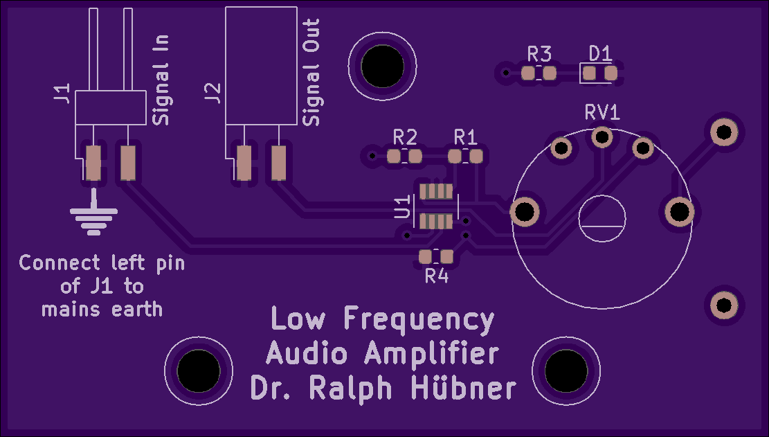
LFAmp - Low Frequency (Audio) Amplifier
2 layer board of 2.22 x 1.26 inches (56.4 x 32.0 mm)
Uploaded:
February 05, 2020
Shared:
February 05, 2020
Total Price:
$14.00
BOM
Contact me if there are questions.
The reason for this Project was the tiny output of my old detector radios which had to be su…
BOM
Contact me if there are questions.
The reason for this Project was the tiny output of my old detector radios which had to be substantially enhanced.
To keep it simple I just wanted to use an opamp to increase the volume by a factor of say 100. Audio signals, however, carry positive and negative voltage levels which means that the opamp had to be provided with both a positive and a negative power rail. I don’t like having two batteries in my design and so I had to find a way to correlate the 0V level of the audio signal to the midst of the available battery voltage.
It is easy to use a voltage divider to generate that mid voltage. However, you can’t tap any power from it without having the tapped voltage wander off because the load circuit changes the resistance ratio of the voltage divider. This means that somehow the tapped voltage has to be stabilized. One way to achieve this is an additional opamp which acts as a buffer, which is why a dual opamp would come in handy. The Analog Devices AD8034 is rail-to-rail and has more than enough of a voltage range.
The PCB offers enough real estate to use 0805 parts and a SOIC-8 chip. I went for 0603 parts and a SOT-23-8 chip instead because there are so few components on this board that its assembly serves as a nice study in soldering smaller structures.
Schematics:

3D Model:

Show full description
BOM
Contact me if there are questions.
The reason for this Project was the tiny output of my old detector radios which had to be su…
BOM
Contact me if there are questions.
The reason for this Project was the tiny output of my old detector radios which had to be substantially enhanced.
To keep it simple I just wanted to use an opamp to increase the volume by a factor of say 100. Audio signals, however, carry positive and negative voltage levels which means that the opamp had to be provided with both a positive and a negative power rail. I don’t like having two batteries in my design and so I had to find a way to correlate the 0V level of the audio signal to the midst of the available battery voltage.
It is easy to use a voltage divider to generate that mid voltage. However, you can’t tap any power from it without having the tapped voltage wander off because the load circuit changes the resistance ratio of the voltage divider. This means that somehow the tapped voltage has to be stabilized. One way to achieve this is an additional opamp which acts as a buffer, which is why a dual opamp would come in handy. The Analog Devices AD8034 is rail-to-rail and has more than enough of a voltage range.
The PCB offers enough real estate to use 0805 parts and a SOIC-8 chip. I went for 0603 parts and a SOT-23-8 chip instead because there are so few components on this board that its assembly serves as a nice study in soldering smaller structures.
Schematics:
3D Model:
Show full description
-
Actions
- Order Board
- Download
- Permalink
- Embed link
Ordering shared project
Hey there! Before ordering, make sure you have all the info you need to complete and use this design. This usually means a component list, and sometimes additional information such as assembly notes, source code, or usage guides.Since this is a project designed by a community member, it may contain design errors that prevent it from working as intended. OSH Park cannot place any guarantees about the functionality or correctness of the design.
- SERVICES
- Upload Your File
- Prototypes
- HELP
- Support
- If you can't find what you're looking for, please contact us at [email protected]
- CONNECT
- Shared Projects
- Log in / Sign up
