Voice Recorder Module Breakout Board
author: ruthsarian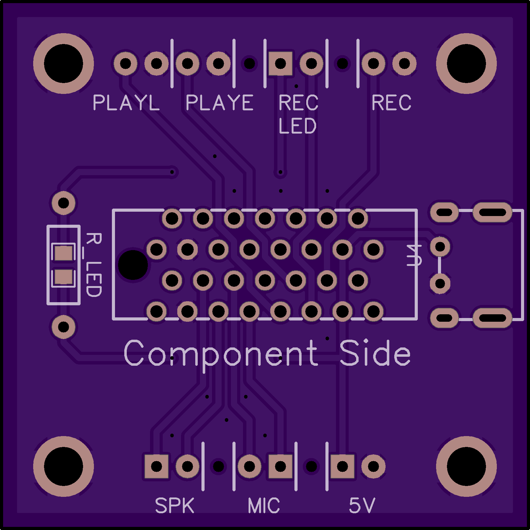
2 layer board of 1.70 x 1.70 inches (43.3 x 43.3 mm)
Uploaded:
March 25, 2026
Shared:
March 25, 2026
Total Price:
$14.50
The Radio Shack Digital Voice Recorder Module (aka VM-1110A, aka ISD-1000A, aka RS #276-1324) was used as the main component of the “guidance chip” prop from the movie “The Rock”. I discovered this while viewing high resolution photos of one of the production props when it went up for auction.
The only other two components are a Takamisawa RZ-12 relay and a Sprague 50uf 16v axial capacitor. With these components I was able to assemble my own version of “The Rock” guidance chip.
I soldered the capacitor and relay in such a way that the digital voice recorder module itself would still remain functional. However to use it I needed a way to interface with it and that is where this PCB comes into play.
The purpose of this board is just to provide a simple interface to the module. It’s centered on an AMP 5650712-1 slot connector which fits the card edge connector on the voice recorder module. On either side of the slot connector are 2.54mm pitch header pins labeled with their functions.
SPK is for connecting a speaker; a generic 0.25W, 8ohm speaker should suffice. The MIC port is for an electret microphone or possibly line-level audio from some other source. PLAYL and PLAYE will trigger playback when the two pins on that port is connected. REC likewise will record audio while its two pins are connected. I use momentary push buttons for these. REC LED can be used to connect an LED to indicate the board is recording. The square pin goes to the anode of the LED. The surface mount resistor labeled R_LED is for limiting current. You could always add your own resistor in series and bridge R_LED.
For power there’s a 5V port on the headers where the square pin is positive and the round is negative, but I’ve also added a footprint for a 2-wire USB port as an alternative means of adding power to the board.
I’ve added holes at the four corners to give you something to use for mounting this to something else. You’ll likely want to use some kind of standoffs to help support the board and elevate it a bit so the pins from the slot connector don’t short on whatever is underneath.
Good luck!
