Sega S Video
author: FrankStrasser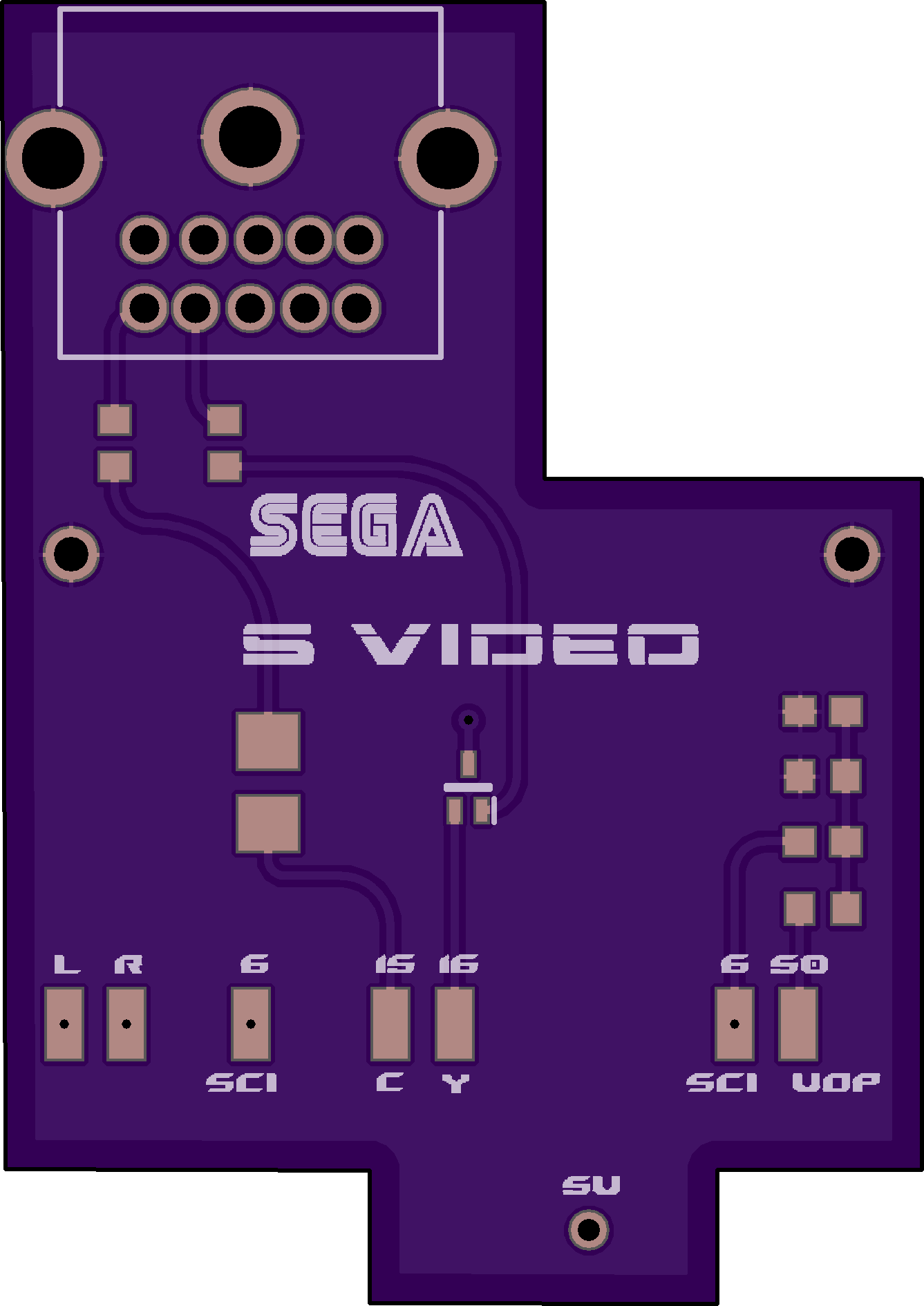
2 layer board of 1.33 x 1.88 inches (33.8 x 47.8 mm)
Uploaded:
May 29, 2025
Shared:
May 29, 2025
Total Price:
$12.50
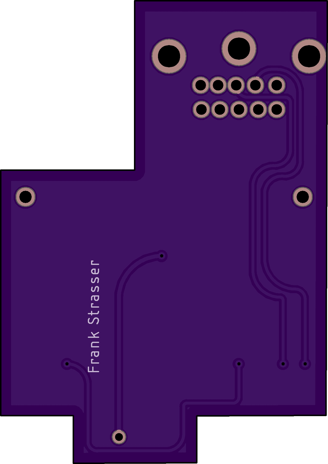
ORDER .8MM FOR BEST FIT. A simple pcb to add s video fuctionality to a model 1 genesis without turning the console shell to swiss cheese. It has an optional subcarrier circuit reroute to reduce jailbars for all video outputs. The connector goes ON TOP of the motherboard, it is a kmdgx 10s bs 10 pin connector so you will need to use a sega saturn s video cable for this. Untested so let me know if it works right but it should be great. the resistor on the luma line (pin 16 pad) is 27 ohms, the transistor on that line is a 2sc4617tlq npn. The resistor on the chroma line(pin 15 pad) is a 75 ohm. The cap on that line is a 3528 tantalum but could probably put a can electro if wanted, positive side facing the pad. For the subcarrier line, first component is a resistor 10k ohms, second component is a capacitor .1uf, third component is a resistor 1k ohms, last component is a 100pf capacitor, all components(including the 2 resistors on the luma chroma lines are 0603 size). to install: first place the connector on top, then solder the pins and flushcut them, then tape the bottom to avoid shorts. then remove the rf box on the console, then add caplegs to the top ground holes on each side, then add a capleg to the rightmost hole for 5v there are 3 round holes it will be the right one but check continuity to a 5v spot to make sure you got the right hole. Then place the board over the rf area and solder down. Pull chroma from pin 15 of the cxa1145 encoder, luma from pin 16 from the encoder, and audio left and right from either the headphone preamp or the headphone jack. For the optional subcarrier restore (recommended) lift pin 50 of the vdp(video processor) and run a wire from it to the pin 50 pad on the pcb. Then run a wire from the pin 6 pad (pin 6 pad next to audio left and right pad for va2-3, pin 6 pad next to vdp pin 50 pad for va6 ( next to it to pin 6 on the cxa1145 encoder. Recommended to remove at least the .1uf cap on the bottom of the board leading to pin 6 on the encoder or all 4 components on the subcarrier line for best working.
ORDER .8MM FOR BEST FIT. A simple pcb to add s video fuctionality to a model 1 genesis without turning the console shell to swiss cheese. It has an optional subcarrier circuit reroute to reduce jailbars for all video outputs. The connector goes ON TOP of the motherboard, it is a kmdgx 10s bs 10 pin connector so you will need to use a sega saturn s video cable for this. Untested so let me know if it works right but it should be great. the resistor on the luma line (pin 16 pad) is 27 ohms, the transistor on that line is a 2sc4617tlq npn. The resistor on the chroma line(pin 15 pad) is a 75 ohm. The cap on that line is a 3528 tantalum but could probably put a can electro if wanted, positive side facing the pad. For the subcarrier line, first component is a resistor 10k ohms, second component is a capacitor .1uf, third component is a resistor 1k ohms, last component is a 100pf capacitor, all components(including the 2 resistors on the luma chroma lines are 0603 size). to install: first place the connector on top, then solder the pins and flushcut them, then tape the bottom to avoid shorts. then remove the rf box on the console, then add caplegs to the top ground holes on each side, then add a capleg to the rightmost hole for 5v there are 3 round holes it will be the right one but check continuity to a 5v spot to make sure you got the right hole. Then place the board over the rf area and solder down. Pull chroma from pin 15 of the cxa1145 encoder, luma from pin 16 from the encoder, and audio left and right from either the headphone preamp or the headphone jack. For the optional subcarrier restore (recommended) lift pin 50 of the vdp(video processor) and run a wire from it to the pin 50 pad on the pcb. Then run a wire from the pin 6 pad (pin 6 pad next to audio left and right pad for va2-3, pin 6 pad next to vdp pin 50 pad for va6 ( next to it to pin 6 on the cxa1145 encoder. Recommended to remove at least the .1uf cap on the bottom of the board leading to pin 6 on the encoder or all 4 components on the subcarrier line for best working.
