QRE1113 Sensor Board V1
author: dewhisna
2 layer board of 0.76 x 0.58 inches (19.2 x 14.8 mm)
Uploaded:
August 22, 2017
Shared:
August 22, 2017
Total Price:
$2.15
This QRE1113 Sensor Board can be used as a Line Sensor, quadrature encoder pickup, object detector, etc. It supports three different modes of operation, configurable, via component selection, as: Raw Sensor, Analog Output Sensor, or Digital Output Sensor.
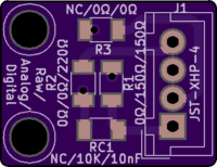
When assembling, select the desired board mode type of raw, analog, or digital depending on your application. The first value listed for each component is the ‘raw’ mode value. The second is the ‘analog’ mode value. The third is the ‘digital’ mode value. “NC” means “No Component”. For example, for a digital mode board, use R1=150 Ohms, R2=220 Ohms, and R3=0 Ohms (jumper), and RC1=10nF (or 0.01uF) capacitor.
All surface mount resistors and capacitors are 1206 footprint for simple, easy hand assembly.
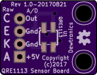
The Pinout in Digital and Analog modes is:
- 1) 5V+ Power In
- 2) Ground
- 3) Ground
- 4) Output
The Pinout in Raw Sensor mode is:
- 1) A (Anode)
- 2) K (Cathode)
- 3) E (Emitter)
- 4) C (Collector)
This board is similar to the two SparkFun Line Sensor Breakout boards https://www.sparkfun.com/products/9453 and https://www.sparkfun.com/products/9454, only more generic in that the same board can be configured either way or used as a raw sensor connection, such as for use with my Modulated Reflectivity Sensor Driver Shield.
The part selection, as detailed on the silkscreen, is identical to the SparkFun design except for the current limiting resistor for the sensor’s Infrared LED. I selected 150 Ohms and the SparkFun design uses 100 Ohms. The difference is approximately 25mA vs 38mA through the LED. The LED is rated at a max of 50mA. According to sensor datasheets, the peak wavelength output characteristics are achieved at 20mA. The higher current may help for slightly longer distance sensing, but will consume more power. You decide which one you wish to use.
For schematics, refer to the SparkFun schematics at the above links for the Digital and Analog modes. The Raw Mode is simply the four pins of the sensor routed to the connector.
The connector chosen is a 4-pin JST XHP series, 2.5mm connector. However, given the minimal difference between 2.5mm and a 0.100" or 2.54mm pitch connector, you should be able to also use a regular 0.100" pitch header connector if so desired.
NOTE: The 10K value shown for RC1 for ‘analog’ mode is low enough to keep the sensor’s phototransistor in the linear region. To push it into the switching region, use a 47K resistor instead to increase the gain nearly five times and make it function adequately for most applications. This is an example where Pololu got it right, but SparkFun didn’t, in my opinion. But, it depends on your application and whether you want the phototransistor in the linear region or switching region.

