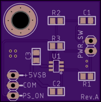
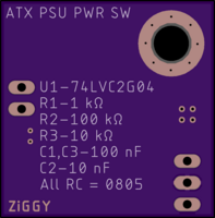
ATX PSU Latching Circuit for Mom Power Switch - Rev.A
author: ziggy587
2 layer board of 0.99 x 1.00 inches (25.1 x 25.4 mm)
Uploaded:
August 16, 2024
Shared:
August 16, 2024
Total Price:
$4.90
This is an updated version of the PCB found here: https://oshpark.com/shared_projects/h6LgDD3k
More info can be found in the above link.
This updated version, Rev.A, is untested. However, there are only minor additions and it should work fine.
The additions are C3, a decoupling capacitor for U1. And the mounting hole now has a stop mask ring around it, exposing the ground plane (ground connection will be made between this PCB and a chassis).
U1 is SOT-23-6 footprint.
Use standard 2.54mm single row pin headers for PWR_SW, this is what an ATX style computer case will use for its power switch.
You can also use 2.54mm pin headers for the +5VSB, COM and PS_ON signals, but I found it to be annoying due to the weight of those wires. I ended up using a 3-pin JST-XH connector here, they are also 2.54mm but more secure since they snap it.

