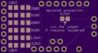
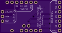
DIY Cell Voltage S.Port Sensor v0.2
author: Pawelsky
2 layer board of 1.30 x 0.70 inches (33.0 x 17.8 mm)
Uploaded:
February 11, 2017
Shared:
February 11, 2017
Total Price:
$4.55
HARDWARE
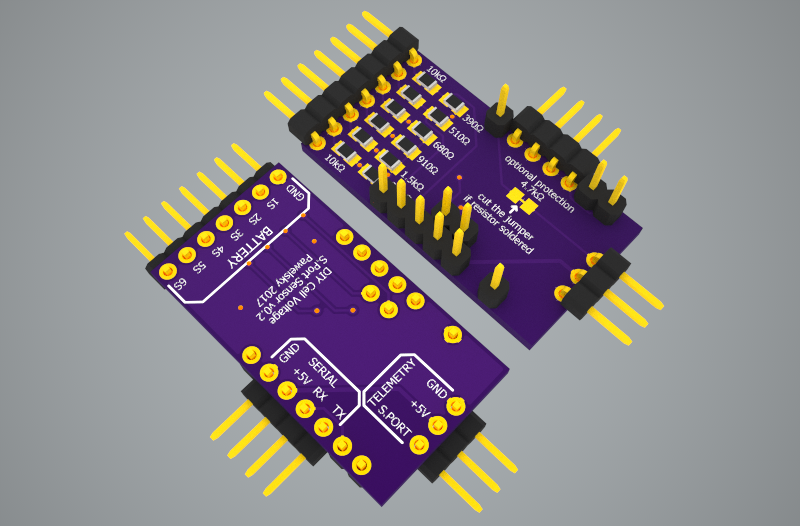
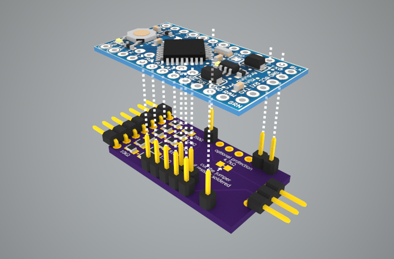
Credit goes to MCfuturegame .. for the Arduino Pro Mini model used in the above rendering.
Required components:
- Arduino Pro Mini 328P/16MHz/5V (with standard Arduino pinout for A4/A5 ports)
- resistors in 0805 package: 6 * 10k, 1 * 390ohm, 1 * 510ohm, 1 * 680ohm, 1 * 910ohm, 1 * 1.5k, 1 * 3.3k (and optionally 1 * 4.7k for protecting the 3.3V S.Port line from 5.0V Arduino serial - cut the jumper between solder pads if you install this resistor)
- 1 * 1x9 straight 2.54mm header pins (divided into 1, 1, 2, 5 sections)
- 1 * 1x14 right angle 2.54mm header pins (divided into 3, 4, 7)
NOTE 1: the 4 pin SERIAL connection is optional and used for uploading the code only - you don’t have to solder it in permanently. Make sure you always connect it TO THE SHIELD, not to the Arduino board itself! When uploading the code the Arduino board needs to be reset manually using the reset button.
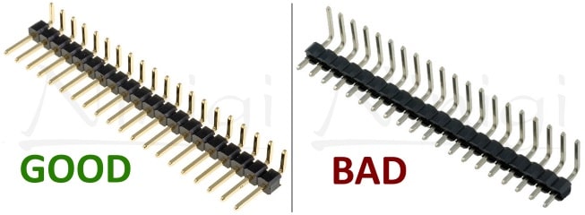
NOTE 2: make sure you order the right angle pin headers that install flat on the board (see the picture below).
SOFTWARE
Load the code below (requires FrSky S-Port Telemetry and standard SoftwareSerial libraries)
/*
  DIY Cell Voltage S-Port Sensor
  (c) Pawelsky 20160123
  Not for commercial use
*/

#include "FrSkySportSensor.h"
#include "FrSkySportSensorFlvss.h"
#include "FrSkySportSingleWireSerial.h"
#include "FrSkySportTelemetry.h"
#include "SoftwareSerial.h"

FrSkySportSensorFlvss flvss;
FrSkySportTelemetry telemetry;

float cell1DividerMultiplier = (10000.0 + 3300.0) / 3300.0 * 1.1 / 1023.0;
float cell2DividerMultiplier = (10000.0 + 1500.0) / 1500.0 * 1.1 / 1023.0;
float cell3DividerMultiplier = (10000.0 +  910.0) /  910.0 * 1.1 / 1023.0;
float cell4DividerMultiplier = (10000.0 +  680.0) /  680.0 * 1.1 / 1023.0;
float cell5DividerMultiplier = (10000.0 +  510.0) /  510.0 * 1.1 / 1023.0;
float cell6DividerMultiplier = (10000.0 +  390.0) /  390.0 * 1.1 / 1023.0;

float cell1Voltage = 0.0;
float cell2Voltage = 0.0;
float cell3Voltage = 0.0;
float cell4Voltage = 0.0;
float cell5Voltage = 0.0;
float cell6Voltage = 0.0;

void setup()
{
  pinMode(A0, INPUT);
  pinMode(A1, INPUT);
  pinMode(A2, INPUT);
  pinMode(A3, INPUT);
  pinMode(A4, INPUT);
  pinMode(A5, INPUT);
  analogReference(INTERNAL);
  telemetry.begin(FrSkySportSingleWireSerial::SOFT_SERIAL_PIN_4, &flvss);
}

void loop()
{
  cell1Voltage = (float)analogRead(A5) * cell1DividerMultiplier;
  cell2Voltage = (float)analogRead(A4) * cell2DividerMultiplier;
  cell3Voltage = (float)analogRead(A3) * cell3DividerMultiplier;
  cell4Voltage = (float)analogRead(A2) * cell4DividerMultiplier;
  cell5Voltage = (float)analogRead(A0) * cell5DividerMultiplier;
  cell6Voltage = (float)analogRead(A1) * cell6DividerMultiplier;
  flvss.setData(cell1Voltage, cell2Voltage - cell1Voltage, cell3Voltage - cell2Voltage,
                cell4Voltage - cell3Voltage, cell5Voltage - cell4Voltage, cell6Voltage - cell5Voltage);
  telemetry.send();
}
This shield is meant for hobbyists and DIYers only. It has not been tested and there are no guarantees it will work. You can download the design file, modify it to your needs and build the board for yourself but you always use it at your own risk!
Not for commercial use!
HARDWARE


Credit goes to MCfuturegame .. for the Arduino Pro Mini model used in the above rendering.
Required components:
- Arduino Pro Mini 328P/16MHz/5V (with standard Arduino pinout for A4/A5 ports)
- resistors in 0805 package: 6 * 10k, 1 * 390ohm, 1 * 510ohm, 1 * 680ohm, 1 * 910ohm, 1 * 1.5k, 1 * 3.3k (and optionally 1 * 4.7k for protecting the 3.3V S.Port line from 5.0V Arduino serial - cut the jumper between solder pads if you install this resistor)
- 1 * 1x9 straight 2.54mm header pins (divided into 1, 1, 2, 5 sections)
- 1 * 1x14 right angle 2.54mm header pins (divided into 3, 4, 7)
NOTE 1: the 4 pin SERIAL connection is optional and used for uploading the code only - you don’t have to solder it in permanently. Make sure you always connect it TO THE SHIELD, not to the Arduino board itself! When uploading the code the Arduino board needs to be reset manually using the reset button.
NOTE 2: make sure you order the right angle pin headers that install flat on the board (see the picture below).

SOFTWARE
Load the code below (requires FrSky S-Port Telemetry and standard SoftwareSerial libraries)
/*
  DIY Cell Voltage S-Port Sensor
  (c) Pawelsky 20160123
  Not for commercial use
*/

#include "FrSkySportSensor.h"
#include "FrSkySportSensorFlvss.h"
#include "FrSkySportSingleWireSerial.h"
#include "FrSkySportTelemetry.h"
#include "SoftwareSerial.h"

FrSkySportSensorFlvss flvss;
FrSkySportTelemetry telemetry;

float cell1DividerMultiplier = (10000.0 + 3300.0) / 3300.0 * 1.1 / 1023.0;
float cell2DividerMultiplier = (10000.0 + 1500.0) / 1500.0 * 1.1 / 1023.0;
float cell3DividerMultiplier = (10000.0 +  910.0) /  910.0 * 1.1 / 1023.0;
float cell4DividerMultiplier = (10000.0 +  680.0) /  680.0 * 1.1 / 1023.0;
float cell5DividerMultiplier = (10000.0 +  510.0) /  510.0 * 1.1 / 1023.0;
float cell6DividerMultiplier = (10000.0 +  390.0) /  390.0 * 1.1 / 1023.0;

float cell1Voltage = 0.0;
float cell2Voltage = 0.0;
float cell3Voltage = 0.0;
float cell4Voltage = 0.0;
float cell5Voltage = 0.0;
float cell6Voltage = 0.0;

void setup()
{
  pinMode(A0, INPUT);
  pinMode(A1, INPUT);
  pinMode(A2, INPUT);
  pinMode(A3, INPUT);
  pinMode(A4, INPUT);
  pinMode(A5, INPUT);
  analogReference(INTERNAL);
  telemetry.begin(FrSkySportSingleWireSerial::SOFT_SERIAL_PIN_4, &flvss);
}

void loop()
{
  cell1Voltage = (float)analogRead(A5) * cell1DividerMultiplier;
  cell2Voltage = (float)analogRead(A4) * cell2DividerMultiplier;
  cell3Voltage = (float)analogRead(A3) * cell3DividerMultiplier;
  cell4Voltage = (float)analogRead(A2) * cell4DividerMultiplier;
  cell5Voltage = (float)analogRead(A0) * cell5DividerMultiplier;
  cell6Voltage = (float)analogRead(A1) * cell6DividerMultiplier;
  flvss.setData(cell1Voltage, cell2Voltage - cell1Voltage, cell3Voltage - cell2Voltage,
                cell4Voltage - cell3Voltage, cell5Voltage - cell4Voltage, cell6Voltage - cell5Voltage);
  telemetry.send();
}
This shield is meant for hobbyists and DIYers only. It has not been tested and there are no guarantees it will work. You can download the design file, modify it to your needs and build the board for yourself but you always use it at your own risk!
