FrSky S.Port to UART adapter v0.1
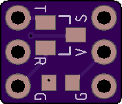
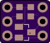
2 layer board of 0.35 x 0.30 inches (9.0 x 7.7 mm)
Uploaded:
March 04, 2019
Shared:
January 08, 2021
Total Price:
$0.50
This FrSky S.Port to UART adapter is a tiny (9x7.7mm) device that allows connecting the single wire, half-duplex inverted FrSky S.Port signal to a regular, non-inverted, two wire UART.
List of components required:
- 2 * 2N7002 MOSFET in SOT-23 package
- 2 * 4.7k SMD resistor in 0603 pa…


Show full description
This FrSky S.Port to UART adapter is a tiny (9x7.7mm) device that allows connecting the single wire, half-duplex inverted FrSky S.Port signal to a regular, non-inverted, two wire UART.
List of components required:
- 2 * 2N7002 MOSFET in SOT-23 package
- 2 * 4.7k SMD resistor in 0603 pa…
Show full description
Voltage divider v0.1

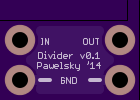
2 layer board of 0.35 x 0.25 inches (8.9 x 6.4 mm)
Uploaded:
August 17, 2014
Shared:
January 30, 2019
Total Price:
$0.40
Just a tiny voltage divider board


Show full description
Just a tiny voltage divider board

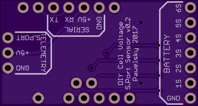
2 layer board of 1.30 x 0.70 inches (33.0 x 17.8 mm)
Uploaded:
February 11, 2017
Shared:
February 11, 2017
Total Price:
$4.55
HARDWARE
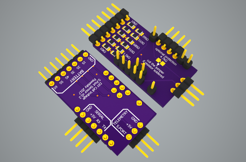
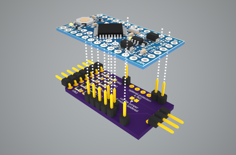
*Credit goes to [MCfuturegame ..](https://3dwarehouse.sketchup.com/model.html?id=u232…
Show full description
HARDWARE
*Credit goes to [MCfuturegame ..](https://3dwarehouse.sketchup.com/model.html?id=u232…
Show full description
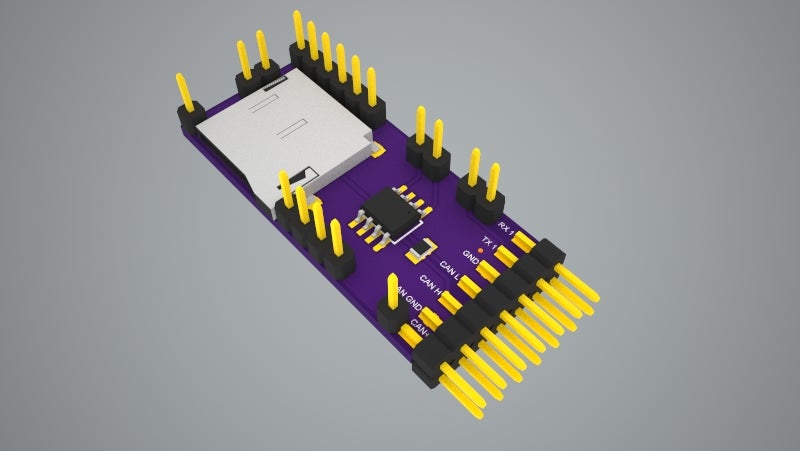
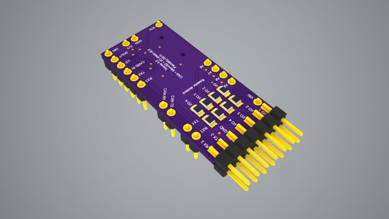
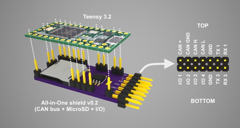
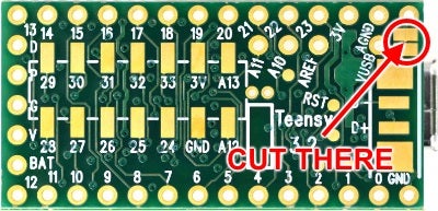
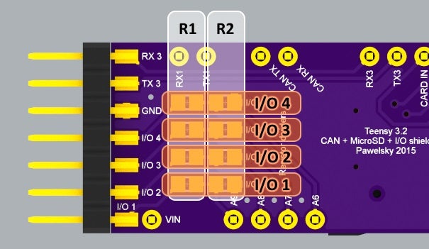
Teensy 3.2 CAN + MicroSD + IO shield v0.2
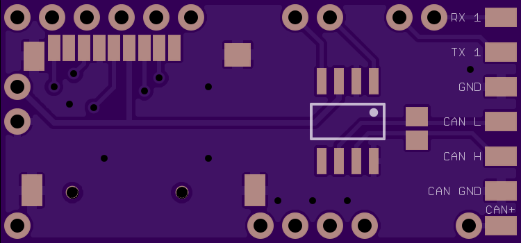
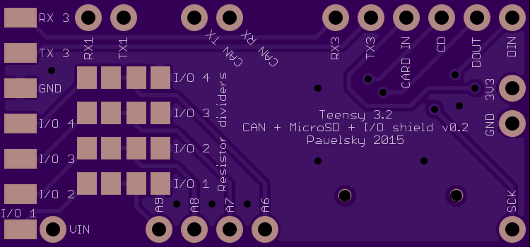
2 layer board of 1.50 x 0.70 inches (38.1 x 17.8 mm)
Uploaded:
October 16, 2015
Shared:
December 18, 2016
Total Price:
$5.25
This Teensy 3.2 shield allows to communicate with the CAN bus with up to 1Mb/s speed. It includes the MicroSD push-push type slot to allow easy data logging. It does not have its own power regulator (which makes it cheaper and easier to build) and relies on Teensy 3.2 built in regulator providin…
Show full description
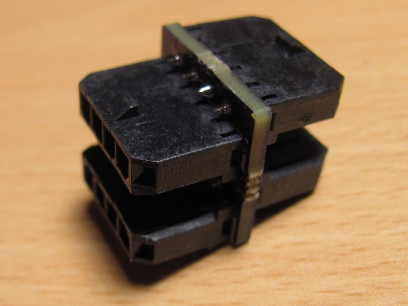
Mini CAN Hub v0.2
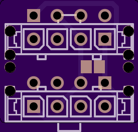
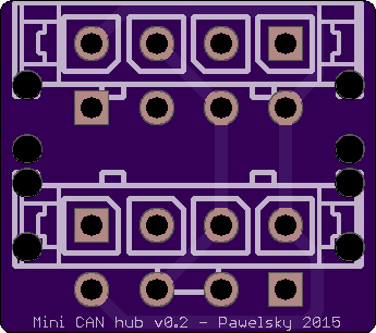
2 layer board of 0.69 x 0.61 inches (17.5 x 15.5 mm)
Uploaded:
July 09, 2015
Shared:
July 29, 2015
Total Price:
$2.10
Mini CAN Hub v0.2 for DJI flight controllers
All you need to assemble this mini hub are 4 Molex Microfit 1x4 vertical PCB headers (43650-0427). When soldering the headers start with the two closer to th…
Show full description
Mini CAN Hub v0.2 for DJI flight controllers
All you need to assemble this mini hub are 4 Molex Microfit 1x4 vertical PCB headers (43650-0427). When soldering the headers start with the two closer to th…
Show full description
