Pogo pin adapter to program the gMUX IC of a MacBook - ver. 0
author: nomeutente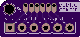
2 layer board of 0.67 x 0.32 inches (17.0 x 8.0 mm)
Uploaded:
October 02, 2019
Shared:
October 02, 2019
Total Price:
$1.05
NOTE: There is a new version of this adapter.
This board is a small and cheap pogo pin programming solution designed in my case for a Lattice HW-USBN-2A (2.54mm pitch pin header) and the gMUX JTAG connector on a logic board of a MacBook Pro 15" early 2011 (pogo pins). This connector is not soldered on the logic board, thus I will use the pogo pins.
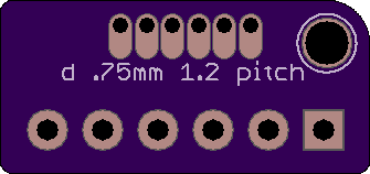
The pogo pins are TH pads with 1.2mm pitch and hole size of .75mm diameter. I will use this pogo pin: P50-J1 or P50-B1. Both have a .68mm diameter. I will solder the ground pin slightly lower so it is the first to make contact when the pogo pins are pressed on the pads.
This PCB has been tested and it works, but I designed a newer better version because the “public domain” text is not readable I added a capacitor between TCK and GND. For the PCB version v0 I soldered the capacitor between the pins of the header.
The hole in the top left is thought to insert a lanyard.
Feel free to do with it whatever you want (public domain)
BOM
| Q.ty | Description |
|---|---|
| 6 | Pogo pins: P50-J1 or P50-B1 |
| 1 | Pin header 1x6 2.54mm |
NOTE: There is a new version of this adapter.
This board is a small and cheap pogo pin programming solution designed in my case for a Lattice HW-USBN-2A (2.54mm pitch pin header) and the gMUX JTAG connector on a logic board of a MacBook Pro 15" early 2011 (pogo pins). This connector is not soldered on the logic board, thus I will use the pogo pins.
The pogo pins are TH pads with 1.2mm pitch and hole size of .75mm diameter. I will use this pogo pin: P50-J1 or P50-B1. Both have a .68mm diameter. I will solder the ground pin slightly lower so it is the first to make contact when the pogo pins are pressed on the pads.
This PCB has been tested and it works, but I designed a newer better version because the “public domain” text is not readable I added a capacitor between TCK and GND. For the PCB version v0 I soldered the capacitor between the pins of the header.
The hole in the top left is thought to insert a lanyard.
Feel free to do with it whatever you want (public domain)
BOM
| Q.ty | Description |
|---|---|
| 6 | Pogo pins: P50-J1 or P50-B1 |
| 1 | Pin header 1x6 2.54mm |
