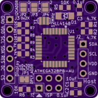
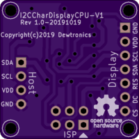
I2C Character Display CPU V1
author: dewhisna
2 layer board of 1.00 x 1.00 inches (25.4 x 25.4 mm)
Uploaded:
October 28, 2019
Shared:
October 28, 2019
Total Price:
$5.00
See also the Updated V2 version of this board which provides SPI display mode support as well.
This board goes inline between a host CPU and an OLED (or similar) I2C graphical display. Its purpose is to convert the graphical display into a character-based display, removing the overhead of font rendering and pixel transfer over the slow I2C bus from the host.
Note that the CPU here is the ATmega328PB (PB version) with dual I2C ports. 12 MHz was chosen for the ceramic resonator, instead of 16MHz or 20 MHz, so that it will run at 3.3v within the specs given in the datasheet. You may, however, be able to overclock it successfully, especially if running at 5v. Be careful, however, of OLED displays with very noisy voltage inverters, as they will interfere with CPU overclocking. I managed to brick two ATmega328PB CPUs trying to run one with this board at 20MHz. 16MHz, however, was no problem.
An identical board with a reversed display connector is also available.
ERRATA: Some I2C displays, like the common SSD1309 2.42" OLED module, require a longer reset pulse than this board currently provides, particularly if the power supply on the display takes a while to settle. If you find your display doesn’t boot correctly, but instead only has a screen garbled with random dots or is otherwise behaving erratically, replace C3 (currently a 0.1uF) with a larger value. It’s recommended to go ahead and make this change during assembly and use a 10uF for C3 of the same ceramic type as C1. During testing, switching C3 from a 0.1uF to a 10uF part has resolved all power-on reset issues encountered.

