TXAnAmp - TX Antenna Amplifier
author: BattleToad
2 layer board of 2.57 x 1.70 inches (65.2 x 43.2 mm)
Uploaded:
April 06, 2021
Shared:
May 22, 2021
Total Price:
$21.75
BOM
Contact me if there are questions.
About a year ago, I have built a small AM radio transmitter (project AMTrans) which was supposed to boadcast audio content over a short range. Although this transmitter does work in principle, its range leaves much to be desired. My idea was to combine this transmitter with a leftover DVBT antenna which I wanted to convert into an active transmission antenna for radio signals.
Unfortunately, I am not exactly an expert in high frequency electronics which is almost voodoo to me. My approach is naively relying on common sense combined with a healthy touch of “bigger is better” :-). The design is based on the dual opamp approach which I have used before e.g. in my curve tracer project. One opamp buffers the central tap of a voltage divider which establishes the positive and negative rail for the second opamp, the one which does the actual amplification.
It turned out that this amplifier circuit interfered with my transmitter and saturated its coupling capacitor over time. Resistor R5 lets this accumulating charge trickle off. I got this idea when I remembered the grid leak of ancient vacuum tube based radio technology. A grid leak is a high-ohmic resistor which either bypasses the coupling capacitor of the grid or connects the grid to the cathode. Both ways the grid’s bias is stabilized by draining those electrons which inside the tube are heading for the anode but accidentally hit the grid. Without the grid leak, a negative charge would accumulate on the grid which would negatively affect the functioning of the tube :-).
The original DVBT antenna was driven by a 6V power supply and at first I intended to reuse this. However, my AD8034 opamps are specified for 24V operation, so why not ramp up the output of the antenna a little bit (which is the bigger - is - better part)? So I ordered a linear 24V power supply from AliExpress and used this instead.
Luckily there is room enough in the housing to solder a two-pin connection header onto the antenna lug. This way, the PCB can be just plugged onto this header and screwed down safely like the original board.
After all, this naive approach to amplfy the antenna signal seems to work. I can receive the radio signal inside a room and even in the adjacent ones. Of cause I have to find a spot without noise from all those switching regulators, but neverthless I call this design a success :-).
Schematics:

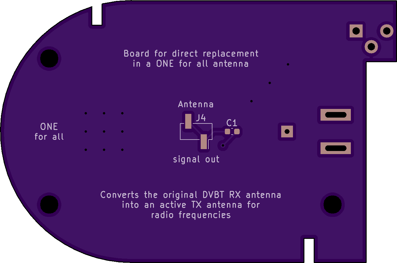
3D Model:


BOM
Contact me if there are questions.
About a year ago, I have built a small AM radio transmitter (project AMTrans) which was supposed to boadcast audio content over a short range. Although this transmitter does work in principle, its range leaves much to be desired. My idea was to combine this transmitter with a leftover DVBT antenna which I wanted to convert into an active transmission antenna for radio signals.
Unfortunately, I am not exactly an expert in high frequency electronics which is almost voodoo to me. My approach is naively relying on common sense combined with a healthy touch of “bigger is better” :-). The design is based on the dual opamp approach which I have used before e.g. in my curve tracer project. One opamp buffers the central tap of a voltage divider which establishes the positive and negative rail for the second opamp, the one which does the actual amplification.
It turned out that this amplifier circuit interfered with my transmitter and saturated its coupling capacitor over time. Resistor R5 lets this accumulating charge trickle off. I got this idea when I remembered the grid leak of ancient vacuum tube based radio technology. A grid leak is a high-ohmic resistor which either bypasses the coupling capacitor of the grid or connects the grid to the cathode. Both ways the grid’s bias is stabilized by draining those electrons which inside the tube are heading for the anode but accidentally hit the grid. Without the grid leak, a negative charge would accumulate on the grid which would negatively affect the functioning of the tube :-).
The original DVBT antenna was driven by a 6V power supply and at first I intended to reuse this. However, my AD8034 opamps are specified for 24V operation, so why not ramp up the output of the antenna a little bit (which is the bigger - is - better part)? So I ordered a linear 24V power supply from AliExpress and used this instead.
Luckily there is room enough in the housing to solder a two-pin connection header onto the antenna lug. This way, the PCB can be just plugged onto this header and screwed down safely like the original board.
After all, this naive approach to amplfy the antenna signal seems to work. I can receive the radio signal inside a room and even in the adjacent ones. Of cause I have to find a spot without noise from all those switching regulators, but neverthless I call this design a success :-).
Schematics:
3D Model:
