GPSDO to Pi cable adapter
author: nsayer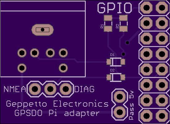
2 layer board of 1.10 x 0.80 inches (27.9 x 20.3 mm)
Uploaded:
September 02, 2017
Shared:
September 19, 2017
Total Price:
$4.40
This board allows you to connect a mini-DIN 6 cable from my GPS Disciplined Oscillator’s diagnostic port to the Raspberry Pi.
The correct part for the mini-DIN 6 jack is the CUI MD-60S. The 3 pin jumper block selects the serial input on the pi to be either the GPS NMEA sentence output or the diagnostic output. The transmit output of the Pi is always connected to the GPS RX pin on the GPSDO. The PPS output of the GPSDO is fed into GPIO 18. The two pin jumper sets whether or not the 5 volt pin from the diagnostic header is connected to the 5 volt bus of the Pi. Powering the Pi from the diagnostic connector is only recommended for the FE-5680A breakout board. Added 5 volt load on the OCXO or TCXO may impact its stability. Attempting to power the oscillator from the Pi is NOT recommended.
Mount a 2x8 .1" DIP female header on the bottom of the board. Install the board on the Pi GPIO header at the left most (pin 1) end. The mini-DIN 6 cable should exit more or less right over the SD card.
The two diodes are just 1N4148s and the two resistors are 10 kΩ.
