W2SG0008iGPSTeensy3.1AddOn.v01x
author: PeskyProducts
2 layer board of 0.71 x 0.76 inches (17.9 x 19.3 mm)
Uploaded:
November 16, 2014
Shared:
November 19, 2014
Total Price:
$2.65
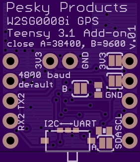
Wi2Wi W2SG0008i 1.575MHz GPS module add-on shield for Teensy 3.1. A mechanical switch toggles between UART and I2C output; 4K7 pullup resistors are on the SDA/SCL lines. Solder jumpers can be used to choose 4800 (default), 9600, and 38400 BAUD rates for NMEA protocol output to UART on Teensy Serial2, I2C supports both 100 kHz and 400 kHz rates. Solder jumpers can be used to take power and ground from the board edge transforming the shield into a conventional breakout board for breadboard use. The shield was designed for the 3V3 VIN of the Teensy but the LDK130 1.8V voltage regulator required by the GPS module can take up to 5.5V as input, making the shield in breakout-board mode ideal for any Arduino platform, even the Arduino UNO. The serial and I2C signals are logic level translated up to VIN on output from the board and down to the 1.8 V of the GPS module’s digital IO on input. There is a small SPDT button switch that sends the required ON/OFF signal to the GPS module. The passive chip antenna placement is less than perfect since it lacks a sufficiently ground-shielded feed line, which is not really wide enough to make the 50 Ohm needed. This is a compromise for the small size of the board, which allows the add-on function without overwhelming the Teensy form factor.
Wi2Wi W2SG0008i 1.575MHz GPS module add-on shield for Teensy 3.1. A mechanical switch toggles between UART and I2C output; 4K7 pullup resistors are on the SDA/SCL lines. Solder jumpers can be used to choose 4800 (default), 9600, and 38400 BAUD rates for NMEA protocol output to UART on Teensy Serial2, I2C supports both 100 kHz and 400 kHz rates. Solder jumpers can be used to take power and ground from the board edge transforming the shield into a conventional breakout board for breadboard use. The shield was designed for the 3V3 VIN of the Teensy but the LDK130 1.8V voltage regulator required by the GPS module can take up to 5.5V as input, making the shield in breakout-board mode ideal for any Arduino platform, even the Arduino UNO. The serial and I2C signals are logic level translated up to VIN on output from the board and down to the 1.8 V of the GPS module’s digital IO on input. There is a small SPDT button switch that sends the required ON/OFF signal to the GPS module. The passive chip antenna placement is less than perfect since it lacks a sufficiently ground-shielded feed line, which is not really wide enough to make the 50 Ohm needed. This is a compromise for the small size of the board, which allows the add-on function without overwhelming the Teensy form factor.
