Z80 Test Circuit
author: SyncChannelBlog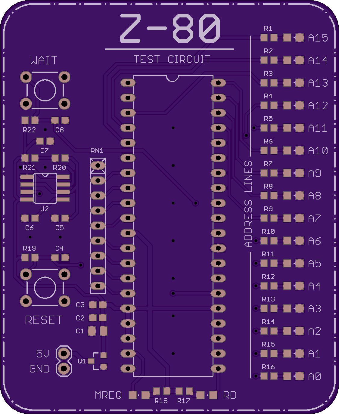
2 layer board of 2.25 x 2.75 inches (57.2 x 69.8 mm)
Uploaded:
September 23, 2017
Shared:
September 23, 2017
Total Price:
$30.90
This board implements a classic Z80 microprocessor test circuit. All data pins are pulled low, causing it to execute the NOP instruction $00 repeatedly. The program counter increments and the activity on the address lines is visualized using LEDs. A slow clock signal is applied to make the address bus activity slow enough to see.
The MREQ and RD pins are also brought out to LEDs. Push buttons are available for the RESET and WAIT lines. The clock signal is generated using a 555 timer.
The board is powered by applying 5V to the 0.1" header pins. Reverse polarity protection is provided using a P-Channel MOSFET.
This board is mostly a novelty. It’s really cool to see the program counter increment on the address pin LEDs and the MREQ and RD LEDs flash. It is not possible to execute an actual program on this board, as it has exactly one byte of “memory” with the contents $00. :)
BOM
- U1: Zilog Z80 40DIP
- U2: 555 Timer 8SOIC
- Q1: Alpha & Omega AO3401A P-Channel MOSFET SOT-23 or similar
- R1-R19, R21-R22: 1k 0603
- R20: 22k 0603
- C1: 10 uF 0805
- C2, C5: 1 uF 0603
- C3-C4, C6-C7: 100 nF 0603
- RN1: 1k, 8 resistor (9 pin) SIP
- A0-A15, MREQ, RD: 0805 SMD LEDs (colors of your choice)
- RESET and WAIT switches: SPST tactile switch Through hole
- 5V header: 1x2 0.1" standard header pins
Notes
- R20, R21, and C5 set the 555 clock signal frequency. The values provided above will set a clock of approximately 32 Hz. You can use an online 555 calculator to pick different values and adjust the clock frequency as you like. In relation to the classic 555 circuit schematic: R21 on this board = R1, R20 = R2, and C5 = C.
- Brand new Z80 microprocessors are available on Digikey if you don’t have one.
Eagle Files
https://github.com/SyncChannel/Z80-Test-Circuit
Other References
http://www.z80.info/z80test0.htm
https://z80project.wordpress.com/2014/02/09/z80-test-circuit/
