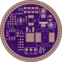
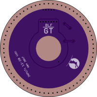
BLF driver GT-buck [rev 04][tried and tested]
author: DEL
2 layer board of 1.82 x 1.82 inches (46.2 x 46.2 mm)
Uploaded:
September 26, 2017
Shared:
December 08, 2017
Total Price:
$16.50
This is the driver used in the production version of the BLF GT light.
[Bunny logo is the property of Lumintop, manufacturer of the GT]
Features
- 2.5 A buck regulator with constant current output
- Attiny85 MCU, supported by NarsilM 1.2 and up firmware
- Most BLF ‘1-channel’ and ‘2-channel’ firmware can be made to work with a few simple changes
- 0.4 V dropout voltage, <150 μA parasitic drain
- Support for button indicator light
Revision changes
- 00 - driver prototype
- 01 - cosmetic changes
- 02 - adapted to the prototype 1 hosts and cell cradles (dedicated ground ring)
- 03 - copper added back to retaining ring area
- 04 - adapted to the production version hosts and cell cradles (retaining ring for ground)
Suggested parts list
| Part no. | Value | Type | Package |
|---|---|---|---|
| C1 | 1u | X7R, 25 V | C0603 |
| C2 | 3.3u - 10u | X5R, 16 V | C0805 |
| C4 | 1u | X7R, 25 V | C0603 |
| C11 | 4u7 | X7R, 50 V | C1206 |
| C12 | 4u7 | X7R, 50 V | C1206 |
| C13 | 4u7 | X7R, 50 V | C1206 |
| C14 | 4u7 | X7R, 50 V | C1206 |
| C15 | 470p | C0G, 50 V | C0603 |
| C16 | 1u | X7R, 25 V | C0603 |
| C17 | 4u7 | X7R, 50 V | C1206 |
| D1 | SS34 | Schottky, 40 V, 3 A | SMC/DO-214AB |
| L1 | 10u | Bourns SRR1208-100ML | 12x12x8 mm |
| Q1 | AOD417 | P-chan <50 mohm <20 nC | TO252 / DPAK |
| R1 | 1M | 1% | R0603 |
| R2 | 47k | 1% | R0603 |
| R3 | 10R | 1% | R0603 |
| R4 | 10k | 1% | R0603 |
| R5 | 3k3 | 1% | R0603 |
| R6 | n/p | ||
| R7 | 1k | 1% | R0603 |
| R8 | 33k | 1% | R0603 |
| R11 | 0R091 | 1%, <300 ppm/C, 1-3 W | R2512 |
| R12 | 47k | 1% | R0603 |
| R13 | n/p | ||
| R14 | 4k7 | 1% | R0603 |
| U1 | ATTINY85-20SU | SOIC-8 | |
| U2 | MIC5235-5 | 5 V LDO regulator | SOT23-5 |
| U3 | LM3409 | Buck controller | HVSSOP-10 |
Output current range is determined by the R4/R5 ratio and the sense resistor (R11) value. R4/R5 could be used to lower the current, but to increase the current R11 should be adjusted:
- Iout = 0.248 / R11 - 0.15
- or R11 = 0.248 / (Iout + 0.15)
(the 0.15 offset is determined by the inductor ripple current and will change if the inductor value or switching frequency is modified)


