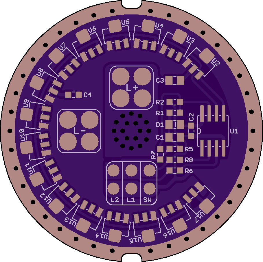
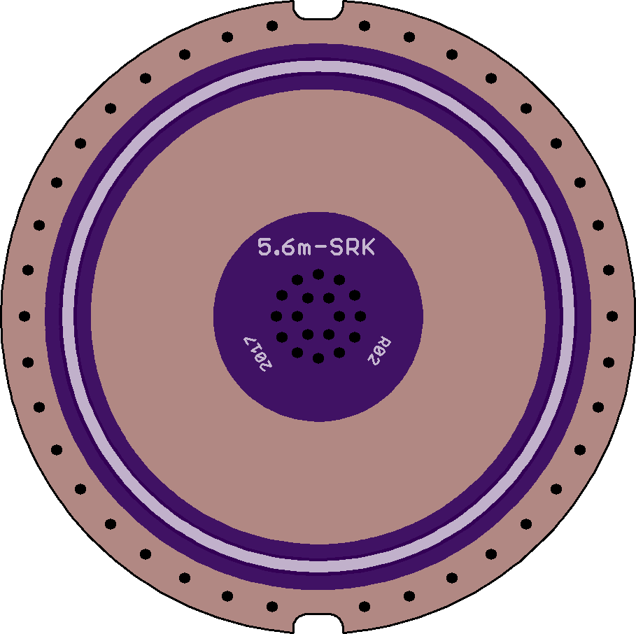
BLF driver GT-buck [rev 04][tried and tested]
2 layer board of 1.82 x 1.82 inches (46.2 x 46.2 mm)
Uploaded:
September 26, 2017
Shared:
December 08, 2017
Total Price:
$16.50
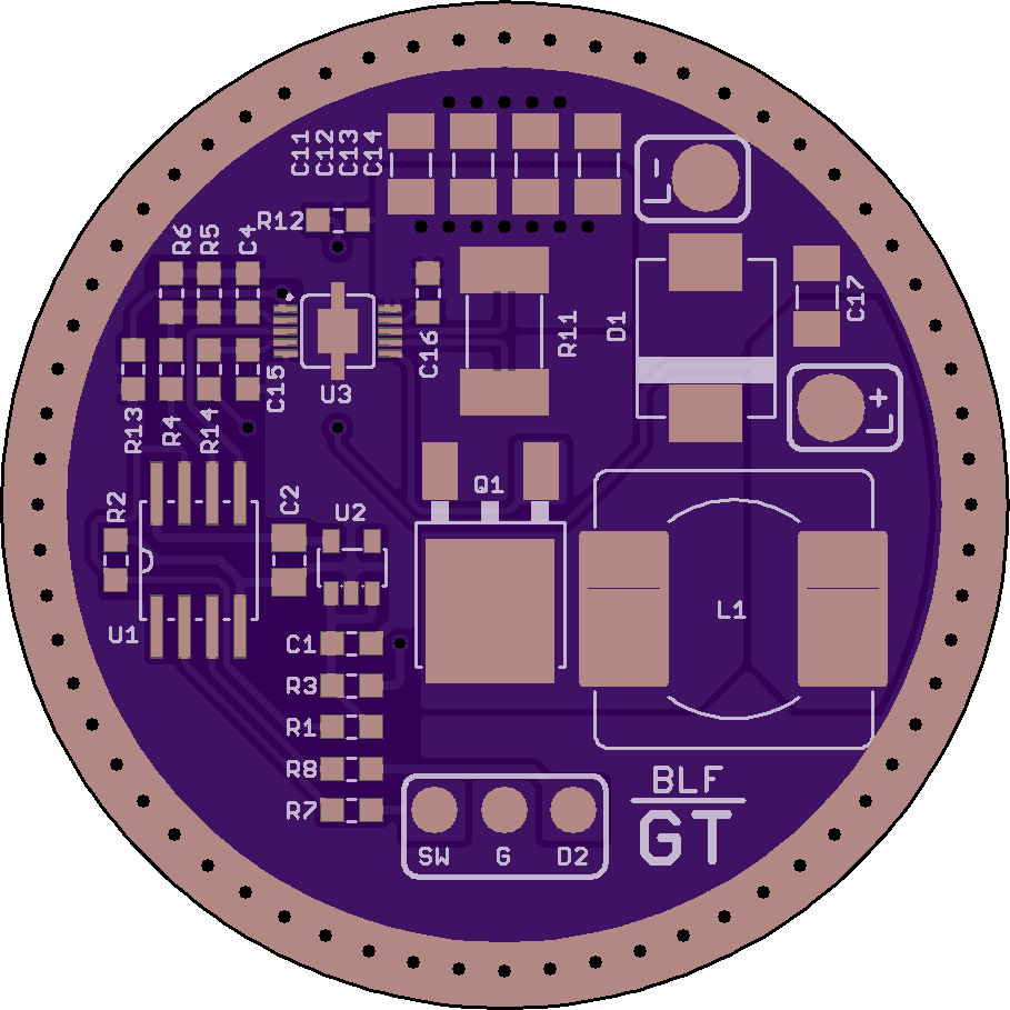
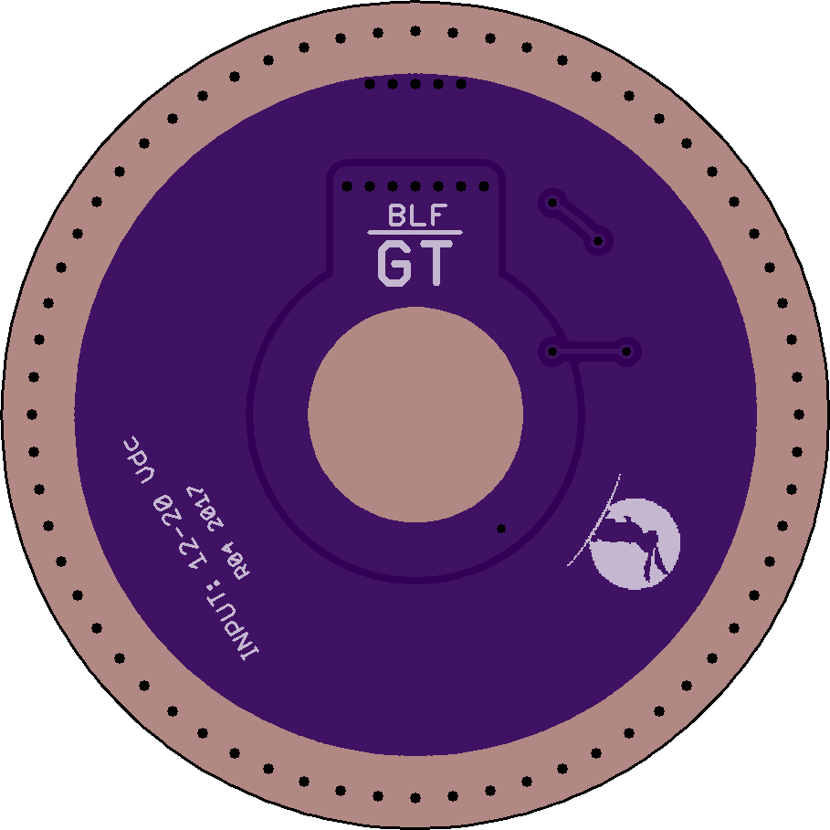
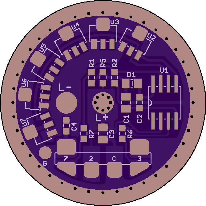
This is the driver used in the production version of the BLF GT light.
[Bunny logo is the property of Lumintop, manufacturer of the GT]
Features
- 2.5 A buck regulator with constant current output
- Attiny85 MCU, supported by NarsilM 1.2 and up firmware
- Most BLF '1-channel' an…

Show full description
This is the driver used in the production version of the BLF GT light.
[Bunny logo is the property of Lumintop, manufacturer of the GT]
Features
- 2.5 A buck regulator with constant current output
- Attiny85 MCU, supported by NarsilM 1.2 and up firmware
- Most BLF '1-channel' an…
Show full description
BLF switch board DDm-K2-SW [rev01][tried and tested]
2 layer board of 0.61 x 0.57 inches (15.4 x 14.4 mm)
Uploaded:
June 02, 2017
Shared:
June 17, 2017
Total Price:
$1.70
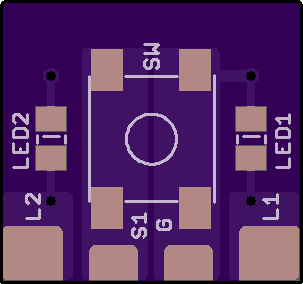
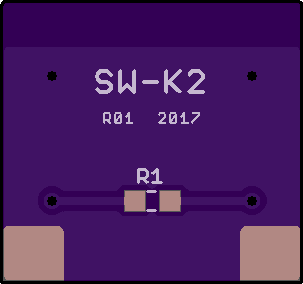
Daughter board for the DDm-K2 driver board.
<https://oshpark.com/shared_projects/F9jb3vFP>
The switch is a NO SMD 6.2x6.2x3.1 mm tactile type. The LEDs have 0805 footprints. Normally R1 is not populated. A jumper or small-value resistor here wires the two LEDs to be driven in parallel.
Daughter board for the DDm-K2 driver board.
<https://oshpark.com/shared_projects/F9jb3vFP>
The switch is a NO SMD 6.2x6.2x3.1 mm tactile type. The LEDs have 0805 footprints. Normally R1 is not populated. A jumper or small-value resistor here wires the two LEDs to be driven in parallel.
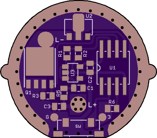
BLF driver 2.1m-K2 [rev00][tried and tested]

2 layer board of 1.34 x 1.34 inches (34.0 x 34.0 mm)
Uploaded:
June 02, 2017
Shared:
June 17, 2017
Total Price:
$8.95
5+1 7135 driver for Solarstorm/Fandyfire K2 lights.
Revision changes
- New
Needs the DDm-K2-SW daughter board for the tactile switch and indicator LEDs:
<https://oshpark.com/shared_projects/0o6V4Iia>
'Standard' BLF parts list, except for:
- R1 and R2 are populated if MCU pin 7…
Show full description
BLF driver DDm-23.2S [rev00a][untested]
2 layer board of 1.02 x 0.89 inches (25.9 x 22.6 mm)
Uploaded:
April 28, 2017
Shared:
April 28, 2017
Total Price:
$4.50
LDO version of the Yezl Y3 driver, for 2S lights.
- Suggested LDO: MIC5235-5.0, SOT23-5
- C1, C2, C3: 4.7 uF (but 2.2 - 10 uF is OK), X5R/X7R
- R5: 10 ohm
LDO version of the Yezl Y3 driver, for 2S lights.
- Suggested LDO: MIC5235-5.0, SOT23-5
- C1, C2, C3: 4.7 uF (but 2.2 - 10 uF is OK), X5R/X7R
- R5: 10 ohm
