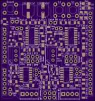
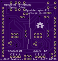
Modulated Reflectivity Sensor Driver V1
author: dewhisna
2 layer board of 2.11 x 2.23 inches (53.5 x 56.7 mm)
Uploaded:
April 06, 2017
Shared:
April 07, 2017
Total Price:
$23.45
The Modulated Reflectivity Sensor Driver Board, a.k.a. the Arduino OptoInterrupter PLL Shield for the ProMini PiDuino HAT, was designed to interface two off-the-shelf optical reflective sensors to the Raspberry Pi via an Arduino ProMini PiDuino HAT.
Unlike the OptoInterrupterShield for ProMini PiDuino HAT, this version uses a Phase Locked Loop (PLL) circuit to modulate the reflectivity sensor to prevent false triggering of the sensor from ambient light.
The optical reflective sensors are used to detect the presence of an object by reflecting an infrared LED back to a phototransistor. The Arduino ProMini on the PiDuino HAT will allow “real-time” sensor timing with an accuracy of +/- 4uSec, using a standard 16MHz ProMini board.
Since the ProMini PiDuino HAT, which this board was designed for, uses standard Arduino Uno footprints, this board can also be used on other Arduino compatible boards. It does, however, require an Arduino board that has 5V compatible I/O pins, as this board is designed to run at 5V.
ERRATA: For proper operation, replace both C2 and C7 with a 0-Ohm Resistor/Jumper (i.e. DC coupling the input instead of AC coupling it). And replace both R1 and R13 with a 0.01uF capacitor.
For a much better frequency adjust range for most sensors, change resistors R7 and R19 from 33K to 47K and install a 180K resistor for both R8 and R20 (both currently labeled “N/A”). This change gives a VCO center-frequency of 14.215 kHz and a usable operating range of 8.79kHz - 20.65kHz, though fold-over on the ends will take it down to about 5.5kHz and up to around 33kHz. The original circuit had a 16.375kHz center-frequency and a range of 4.75kHz to 55.5kHz. But most sensors prefer 10kHz-12kHz and seldom function well above 25kHz.
The non-inverted PC2 output and/or the inverted ~PC2 output are the preferred output selections. PCP and ~PCP selections work, but need more signal post-processing.
For sensor input, use non-inverted PC2 Output for an Active Low output and inverted ~PC2 for an Active High output.
For push-button operation (either on-board push-buttons or an external push-button connected across “K” and “C” terminals), there are two options:
1) Without the sensor connected: add a 0.1uF cap across the “K” and “C” terminals (i.e. across the push-button). With this configuration, the non-inverted PC2 output will be Active Low and the inverted ~PC2 output will be Active High.
2) With the sensor still connected: Force the sensor into reflection, by placing a reflective target in front of it. No additional 0.1uF capacitor is needed in this configuration. But, the non-inverted PC2 output will be Active High and the inverted ~PC2 output will be Active Low, the opposite of the other configurations.
Note: All surface mount discrete components are 1206 footprint.

