(tr)uSDX TCXO Upgrade
author: SyncChannelBlog
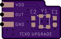
2 layer board of 0.59 x 0.39 inches (15.0 x 10.0 mm)
Uploaded:
August 14, 2022
Shared:
August 14, 2022
Total Price:
$1.15
🔴 I recommend ordering this board with the 2 Layer 2oz 0.8mm “Half Height” Service. 🔴
This PCB allows you to upgrade the (tr)uSDX HF radio with a Temperature Compensated Crystal Oscillator (TCXO) for improved frequency accuracy and stability. The (tr)uSDX uses a standard 27 MHz crystal for frequency synthesis and has no provision on the main board for upgrading with a TCXO. This board adheres to the main board and connects to three pads to power the TCXO and provide the new clock signal to the PLL chip.
Please be aware that assembling and installing this board involves fine SMD soldering and removing the stock crystal from the main board in the radio. Removing the crystal involves some small risk of damaging the board just like removing any part, and damaging the PLL circuit would render the radio inoperable. Proceed with caution if you decide to perform this mod.
This mod is not “official” in any way or associated with the (tr)uSDX project, other than that I am a user of the radio and wanted to contribute a useful mod that I developed to the community.
Parts List:
Note: I have tested the TCXO above so I know it works, but you should be able to substitute other 27 MHz TCXOs that have a 3.20mm x 2.50mm package and operate on 3.3V.
Board Files:
Eagle files are available on GitHub: (truSDX-TCXO-Upgrade)
The PCB uploaded here on OSHPark is Rev B of the PCB. Rev A was an early version of the board that I made for testing. There is no reason to order it instead, but I have included it in the GitHub repo in case someone wants it.
Assembly:
Assembly of this board is straightforward if you are comfortable soldering very small SMD components. Please do watch the orientation of the TCXO. There is a small dot on the PCB to indicate pin 1.

Testing the Board:
If possible, test the board after assembly to make sure the TCXO is oscillating correctly before installing it in the radio. Ideally the waveform should be verified on an oscilloscope and the frequency measured with a counter. The waveform from the ECS TCXO is a ~1.2 Vpp clipped sine wave and the frequency should be 27.000000 MHz +/- 54 Hz (2 ppm).
Install Photos:
Installation requires the removal of the stock 27 MHz crystal, Y1, from the main board. A hot air gun is the most common way to do this, but please be careful that you do not disturb or blow off any neighboring parts. I personally used ChipQuik instead. Removing the crystal frees up pads for the TCXO output connection and ground. VDD is obtained from one end of diode D2 which is next to the crystal footprint as shown.

Next, test fit the TCXO board on the main board. You need to line up the three castellations/pads for VDD, OUT and GND with the three pads on the main board shown above. The castellations should be directly over the pads or set back slightly to allow access for soldering.
There is unfortunately no where to screw down or otherwise secure the TCXO board to the main board, so it will need to be adhered in some way. I made the board big enough that it overlaps with nearby chips and parts, so there is plenty of surface area to use glue or double sided tape. I used a piece of double sided tape that covered almost the entire underside of the TCXO board, and it makes good contact with U6, U3, D1 and D2. You could further use some epoxy, hot melt glue, and/or kapton tape to secure the board.

Now you need to make a connection between VDD, OUT and GND on the TCXO board and the respective pads below. I used small tinned wire to do this. With a long piece of wire in hand, lay it vertically in the castellation and extending down to touch the pad. Solder the end of the wire to the pad on the main board, then trim the wire flush with the top of the TCXO board, then solder the wire into the castellation and/or on the pad.
The castellated vias are spaced 0.1"/2.54mm apart, so you could theoretically use standard pin header instead of tinned wire. However, you will need to trim the pins very short to keep the height of the TCXO board to a minimum. It might not be clear in the zoomed in pictures, but the space between the mod board and the main board is very small. I think tinned wire as shown is the best way to make the connection, but you may find some more creative approach.

With the TCXO mod installed, re-assemble the radio and test it to make sure you can change frequencies and receive and transmit. If you had previously performed a frequency calibration and changed the value of setting 8.3 Ref freq, you will want to reset this to 27000000. TCXOs aren’t perfect, and based on the exact oscillation frequency of yours you may find that a setting of 27000050 or 26999950 is more accurate. Either way, it should be much more accurate than the default crystal.
I have performed this mod on two of my (tr)uSDX radios with good results. Good luck if you decide to attempt the mod yourself!
🔴 I recommend ordering this board with the 2 Layer 2oz 0.8mm “Half Height” Service. 🔴
This PCB allows you to upgrade the (tr)uSDX HF radio with a Temperature Compensated Crystal Oscillator (TCXO) for improved frequency accuracy and stability. The (tr)uSDX uses a standard 27 MHz crystal for frequency synthesis and has no provision on the main board for upgrading with a TCXO. This board adheres to the main board and connects to three pads to power the TCXO and provide the new clock signal to the PLL chip.
Please be aware that assembling and installing this board involves fine SMD soldering and removing the stock crystal from the main board in the radio. Removing the crystal involves some small risk of damaging the board just like removing any part, and damaging the PLL circuit would render the radio inoperable. Proceed with caution if you decide to perform this mod.
This mod is not “official” in any way or associated with the (tr)uSDX project, other than that I am a user of the radio and wanted to contribute a useful mod that I developed to the community.
Parts List:
Note: I have tested the TCXO above so I know it works, but you should be able to substitute other 27 MHz TCXOs that have a 3.20mm x 2.50mm package and operate on 3.3V.
Board Files:
Eagle files are available on GitHub: (truSDX-TCXO-Upgrade)
The PCB uploaded here on OSHPark is Rev B of the PCB. Rev A was an early version of the board that I made for testing. There is no reason to order it instead, but I have included it in the GitHub repo in case someone wants it.
Assembly:
Assembly of this board is straightforward if you are comfortable soldering very small SMD components. Please do watch the orientation of the TCXO. There is a small dot on the PCB to indicate pin 1.

Testing the Board:
If possible, test the board after assembly to make sure the TCXO is oscillating correctly before installing it in the radio. Ideally the waveform should be verified on an oscilloscope and the frequency measured with a counter. The waveform from the ECS TCXO is a ~1.2 Vpp clipped sine wave and the frequency should be 27.000000 MHz +/- 54 Hz (2 ppm).
Install Photos:
Installation requires the removal of the stock 27 MHz crystal, Y1, from the main board. A hot air gun is the most common way to do this, but please be careful that you do not disturb or blow off any neighboring parts. I personally used ChipQuik instead. Removing the crystal frees up pads for the TCXO output connection and ground. VDD is obtained from one end of diode D2 which is next to the crystal footprint as shown.

Next, test fit the TCXO board on the main board. You need to line up the three castellations/pads for VDD, OUT and GND with the three pads on the main board shown above. The castellations should be directly over the pads or set back slightly to allow access for soldering.
There is unfortunately no where to screw down or otherwise secure the TCXO board to the main board, so it will need to be adhered in some way. I made the board big enough that it overlaps with nearby chips and parts, so there is plenty of surface area to use glue or double sided tape. I used a piece of double sided tape that covered almost the entire underside of the TCXO board, and it makes good contact with U6, U3, D1 and D2. You could further use some epoxy, hot melt glue, and/or kapton tape to secure the board.

Now you need to make a connection between VDD, OUT and GND on the TCXO board and the respective pads below. I used small tinned wire to do this. With a long piece of wire in hand, lay it vertically in the castellation and extending down to touch the pad. Solder the end of the wire to the pad on the main board, then trim the wire flush with the top of the TCXO board, then solder the wire into the castellation and/or on the pad.
The castellated vias are spaced 0.1"/2.54mm apart, so you could theoretically use standard pin header instead of tinned wire. However, you will need to trim the pins very short to keep the height of the TCXO board to a minimum. It might not be clear in the zoomed in pictures, but the space between the mod board and the main board is very small. I think tinned wire as shown is the best way to make the connection, but you may find some more creative approach.

With the TCXO mod installed, re-assemble the radio and test it to make sure you can change frequencies and receive and transmit. If you had previously performed a frequency calibration and changed the value of setting 8.3 Ref freq, you will want to reset this to 27000000. TCXOs aren’t perfect, and based on the exact oscillation frequency of yours you may find that a setting of 27000050 or 26999950 is more accurate. Either way, it should be much more accurate than the default crystal.
I have performed this mod on two of my (tr)uSDX radios with good results. Good luck if you decide to attempt the mod yourself!

