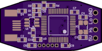
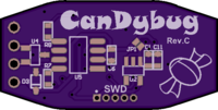
CanDybug
author: IntergatedCircuits
2 layer board of 1.19 x 0.60 inches (30.2 x 15.3 mm)
Uploaded:
November 11, 2018
Shared:
November 11, 2018
Total Price:
$3.55
Cheap open-source full-featured CAN bus traffic analyzer.
Repository
The schematic and the embedded firmware for the onboard STM32 chip are available on GitHub.
Bill of Materials
(All passive components and LEDs are 0603 footprint, italics indicate optional features.)
- USB-Micro-B connector
- 2 x 100 mil header CAN / 4 x 100 mil header CAN + 5V
- 5 x 50 mil header SWD programming interface
- U1: TPD3S014DBVR (for USB ESD protection and transceiver power control) - alternatively short JP1, or power the transceiver via external 5V
- U2: TPS70933DBVR or equivalent (5Vin 3.3Vout 100mA LDO)
- U3: STM32F042C6T6 or equivalent (USB+CAN)
- U4: TPD2E009DBZR (for CAN ESD protection)
- U5: SN65HVD255DR or equivalent (any SOIC-8 CAN transceiver)
- D3: 5.6V Zener diode SOD-323 (only if 5V power isn’t from USB)
- X1: 3.2 x 2.5 mm 8/12 MHz quartz
- C3, C4: 22pF (quartz load capacitors)
- C1, C11: 1uF
- D1, D2: frame and error indicating LED (e.g. green and red)
- R5, R6: adjust according to desired LED current
- C5, C6, C7, C8, C9, C10: 100nF
- R7, R8 depend on the CAN transceiver, typically R7 = 0
- R1: 1.5kO (only if STM32F1 or STM32F3 series is used)
- R4: 1MO
- C2: 10nF

