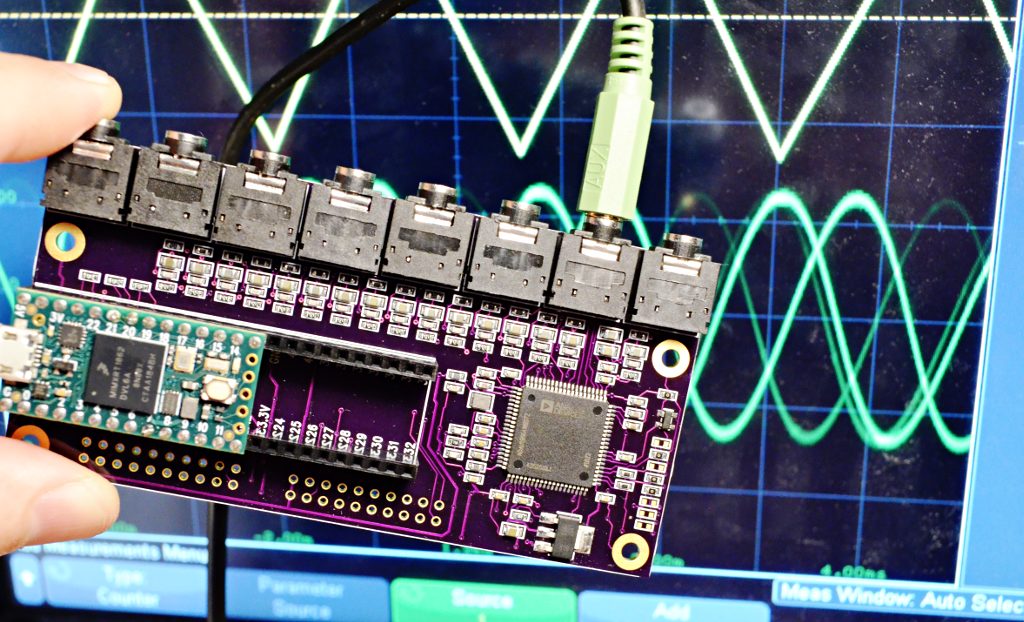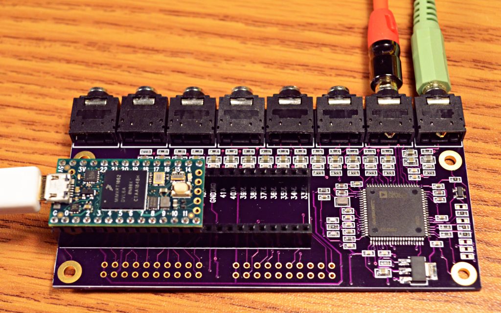
So far this PCB has only been tested with the code below. It does produce 16 different waveforms output with the correct frequencies and waveform shapes. The board seems to work, but no other testing has yet been done (or perhaps by the time you’re reading this, maybe this page is old info….)
Sharing this because it was requested on this Tweet.
https://twitter.com/insolace/status/1342452185552932864
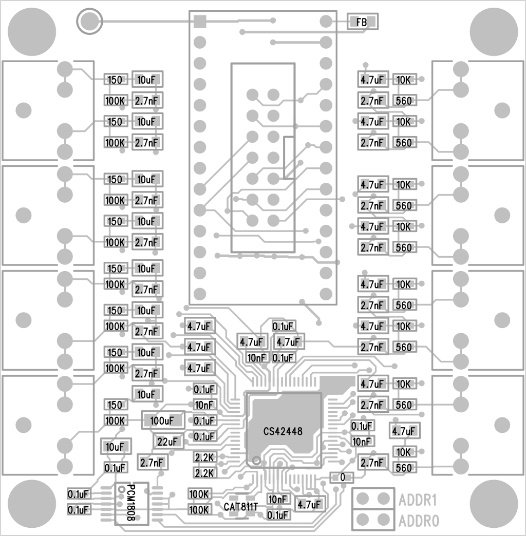
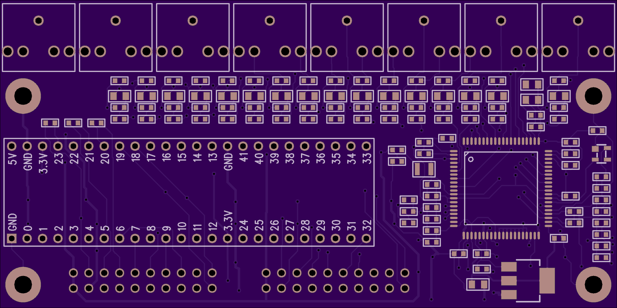
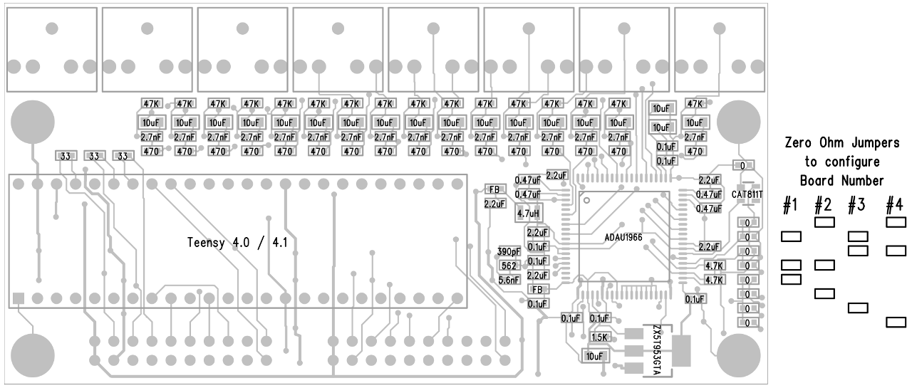
This board uses the ADAU1966A chip from Analog Devices. Analog Devices also made an older version of this chip, ADAU1966 without the “A”. It is listed as not recommended for new designs. If you search and find the old chip, don’t worry. Just make sure you’re searching for ADAU1966A with the “A”.
#include <Audio.h>
#include <Wire.h>

// GUItool: begin automatically generated code
AudioSynthWaveform       waveform6; //xy=220,287
AudioSynthWaveform       waveform5; //xy=221,250
AudioSynthWaveform       waveform7; //xy=221,325
AudioSynthWaveform       waveform2;      //xy=222,134
AudioSynthWaveform       waveform10; //xy=221,437
AudioSynthWaveform       waveform1;      //xy=223,97
AudioSynthWaveform       waveform8; //xy=222,363
AudioSynthWaveform       waveform9; //xy=222,400
AudioSynthWaveform       waveform3;      //xy=223,172
AudioSynthWaveform       waveform11; //xy=222,475
AudioSynthWaveform       waveform4;      //xy=224,210
AudioSynthWaveform       waveform12; //xy=223,513
AudioSynthWaveform       waveform14; //xy=223,588
AudioSynthWaveform       waveform13; //xy=224,551
AudioSynthWaveform       waveform15; //xy=224,626
AudioSynthWaveform       waveform16; //xy=225,664
AudioOutputTDM           tdm1;           //xy=524,345
AudioConnection          patchCord1(waveform6, 0, tdm1, 5);
AudioConnection          patchCord2(waveform5, 0, tdm1, 4);
AudioConnection          patchCord3(waveform7, 0, tdm1, 6);
AudioConnection          patchCord4(waveform2, 0, tdm1, 1);
AudioConnection          patchCord5(waveform10, 0, tdm1, 9);
AudioConnection          patchCord6(waveform1, 0, tdm1, 0);
AudioConnection          patchCord7(waveform8, 0, tdm1, 7);
AudioConnection          patchCord8(waveform9, 0, tdm1, 8);
AudioConnection          patchCord9(waveform3, 0, tdm1, 2);
AudioConnection          patchCord10(waveform11, 0, tdm1, 10);
AudioConnection          patchCord11(waveform4, 0, tdm1, 3);
AudioConnection          patchCord12(waveform12, 0, tdm1, 11);
AudioConnection          patchCord13(waveform14, 0, tdm1, 13);
AudioConnection          patchCord14(waveform13, 0, tdm1, 12);
AudioConnection          patchCord15(waveform15, 0, tdm1, 14);
AudioConnection          patchCord16(waveform16, 0, tdm1, 15);
AudioControlCS42448      cs42448_1;      //xy=554,546
// GUItool: end automatically generated code


#define ADAU1966A_PLL_CLK_CTRL0  0x00
#define ADAU1966A_PLL_CLK_CTRL1  0x01
#define PDN_THRMSENS_CTRL_1      0x02
#define ADAU1966A_DAC_CTRL0      0x06
#define ADAU1966A_DAC_CTRL1      0x07
#define ADAU1966A_DAC_CTRL2      0x08
uint8_t i2c_addr = 0x04;

bool write(uint8_t address, uint32_t data) {
  Wire.beginTransmission(i2c_addr);
  Wire.write(address);
  Wire.write(data);
  if (Wire.endTransmission() != 0) return false;
  return true;
}

uint8_t read(uint8_t address) {
  Wire.beginTransmission(i2c_addr);
  Wire.write(address);
  if (Wire.endTransmission(false) != 0) return 0;
  if (Wire.requestFrom((int)i2c_addr, 1) < 1) return 0;
  return Wire.read();
}


// 1. Apply power to the ADAU1966A
// 2. Assert the PU/RST pin high after power supplies are stable.
// 3. Set the PUP bit to 1.
// 4. Program all necessary registers for the desired settings.
// 5. Set the MMUTE bit to 0 to unmute all channels.

bool adau1966_begin() {
  Wire.begin();
  // 3. Set the PUP bit to 1.  (also disable crystal oscillator)
  if (!write(ADAU1966A_PLL_CLK_CTRL0, 0x00110101)) return false;

  // 4. Program all necessary registers for the desired settings.
  //  using external MCLK

  // set MCLK from MCLKI or XTALI
  if (!write(ADAU1966A_PLL_CLK_CTRL1, 0b00110011)) return false;

  // When using the ADAU1966A in direct master clock mode, power
  // down the PLL in the PDN_THRMSENS_CTRL_1 register.
  if (!write(PDN_THRMSENS_CTRL_1, 0b00100010)) return false;

  // TDM16 needs LRCLK_MODE set to pulse
  if (!write(ADAU1966A_DAC_CTRL1, 0b01000000)) return false;

  // TDM16 needs 16 bits per slot
  if (!write(ADAU1966A_DAC_CTRL2, 0b00010000)) return false;

  // 5. Set the MMUTE bit to 0 to unmute all channels.
  //  sets TDM16 mode

  if (!write(ADAU1966A_DAC_CTRL0, 0b00100000)) return false;

  return true;
}

void setup() {
  AudioMemory(50);
  //cs42448_1.enable();
  //cs42448_1.volume(1.0);
  while (!Serial) ;
  Serial.println("ADAU1966A Test");
  if (adau1966_begin()) {
    Serial.println("configured ADAU1966A");
  } else {
    Serial.println("failed to config ADAU1966A");
    if (cs42448_1.enable() && cs42448_1.volume(1.0)) {
      Serial.println("configured CS42448");
    } else {
      Serial.println("failed to config CS42448");
    }
  }
  waveform1.begin(0.95, 207.65, WAVEFORM_TRIANGLE);
  waveform2.begin(0.95, 220.00, WAVEFORM_SINE);
  waveform3.begin(0.95, 233.08, WAVEFORM_SAWTOOTH);
  waveform4.begin(0.95, 246.94, WAVEFORM_SQUARE);
  waveform5.begin(0.95, 261.63, WAVEFORM_TRIANGLE);
  waveform6.begin(0.95, 277.18, WAVEFORM_SINE);
  waveform7.begin(0.95, 293.66, WAVEFORM_SAWTOOTH);
  waveform8.begin(0.95, 311.13, WAVEFORM_SQUARE);
  waveform9.begin(0.95, 329.63, WAVEFORM_TRIANGLE);
  waveform10.begin(0.95, 349.23, WAVEFORM_SINE);
  waveform11.begin(0.95, 369.99, WAVEFORM_SAWTOOTH);
  waveform12.begin(0.95, 392.00, WAVEFORM_SQUARE);
  waveform13.begin(0.95, 415.30, WAVEFORM_TRIANGLE);
  waveform14.begin(0.95, 440.00, WAVEFORM_SINE);
  waveform15.begin(0.95, 466.16, WAVEFORM_SAWTOOTH);
  waveform16.begin(0.95, 493.88, WAVEFORM_SQUARE);
}

void loop() {
}