Multi Frequency Oscillator
author: skum
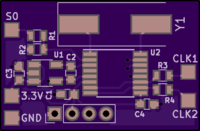
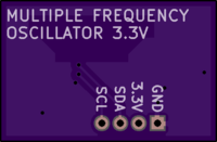
2 layer board of 0.92 x 0.61 inches (23.4 x 15.4 mm)
Uploaded:
August 13, 2018
Shared:
September 16, 2018
Total Price:
$2.75
A revision B that is physically smaller, but functionally identical here
Idea taken from https://nfggames.com/forum2/index.php?topic=5744.0 but since I sometimes needed to switch two frequencies, I made this. Example where it is usable, is when a PSX switches between NTSC and PAL, it needs to switch both the carrier frequency of the video signal AND the clock frequency to the DAC to have a proper video signal that doesn’t go black and white and so on.
Parts list:
- U1 1.8V LDO Regulator, here a TPS78218 (Mouser P/N: 595-TPS78218DDCT)
- U2 Texas Instruments CDCE925 (Mouser P/N: 595-CDCE925PWR)
- C1 1uF 0603 SMD capacitor
- C2 1uF 0603 SMD capacitor
- C3 1uF 0603 SMD capacitor
- C4 1uF 0603 SMD capacitor
- R1 10K 0603 SMD resistor
- R2 10K 0603 SMD resistor
- R3 18R 0603 SMD resistor (or whatever needed to accomodate signal to the circuit)
- R4 18R 0603 SMD resistor (or whatever needed to accomodate signal to the circuit)
- Y1 27MHz crystal ((Mouser P/N: 774-ATS270BSM-1E or the shallower 815-ABLS3-27MD4YFT)
Use 0.8mm substrate for a shallow profile.
Note that Y2 and Y4 are parallel coupled, same with Y3 and Y5. Thus if programming with TI’s ClockPro software, Y4 must be tri-stated when Y2 output is on, and Y5 should be tri-stated when Y3 is on. Of course also vice-versa.
More info here

