Pedestrian Crossing for the Raspberry Pi v0.1
author: Opabinia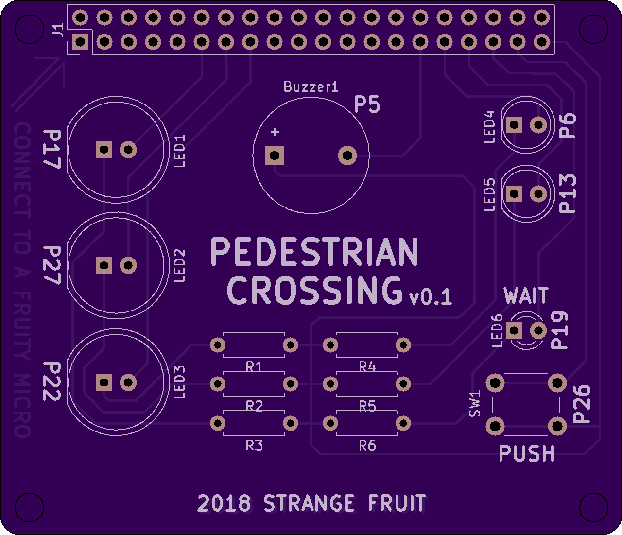
2 layer board of 2.56 x 2.20 inches (65.0 x 55.9 mm)
Uploaded:
February 18, 2018
Shared:
March 14, 2018
Total Price:
$28.15
Note (180314): This board has been tested and found to be working according to expectations! Correction of some minor design flaws is underway! A new but untested design is available here: https://oshpark.com/shared_projects/uIL9j2Ex
The quick and dirty mockup code is available here: https://github.com/overengen/Pedestrian_Crossing_for_the_RPi
Warning! This board hasn’t been tested yet, but the mock-up did work as intended but there might still be issues that needs to be addressed such as the “be or not to be” capacitor placed over the buzzer. And then there is this tiny detail about the order of LEDs and resistors… Mounting holes are missing, and the board might be ½ mm to short. Watch out for future revisions!
This is my first attempt to design a PCB for the Raspberry Pi. It’s a dead simple design and supposed to fit on top of a Raspberry Pi (65x56.5mm). With a bit of coding the Raspberry Pi should be able to control all the LEDs, the buzzer and read the push button. My intention is to use this as a base for a coding project at school. Pin numbers (connecting to the switch, the buzzer and the LEDs) are written on the surface of the PCB as a reference in order to make coding a bit easier.
BOM:
3 x 10mm LEDs (red, yellow, green).
2 x 5mm LEDs (red, green).
1 x 3mm LED (yellow or white).
1 x Switch 4pins, 6mm.
1 x Buzzer
6 x Resistors (~50 Ohm)
1 x Connector (20x2)
