M100 8K RAM Module (Surface Mount)
author: Stardust
2 layer board of 0.82 x 1.40 inches (20.8 x 35.6 mm)
Uploaded:
October 24, 2021
Shared:
October 24, 2021
Total Price:
$5.70
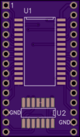
Memory module for the Radio Shack M100 using surface mount components.
Spec standby current for selected RAM is 0.5uA.
The parts are available from Digi Key or Mouser. U1 and U2 are surface mount parts. You may also be able to find them cheaper elsewhere.
U1 = AS6C6264-55SCN U2 = SN74HC86IDRG4Q1 PINS = TE 1544210-2 SIL Connectors
Assembly Tips
To simplify the construction the following assembly order is recommended:
- Solder on U1 and U2.
- The CTS 2180 ETAME IC pins are then soldered on to the board. The easiest method is to use an empty IC socket on the M100 to make sure they are the correct length.
How to use the IC Pins (CTS 2180)
The suggested pins used for inserting the module into the M100 IC socket are similar to IC pins and should not cause any problems with the socket. The pins are used in a slightly different way to the usual method shown in their datasheet, they are normally used for mounting SIL boards vertically via their edge.
- Cut a strip of pins to the required length, 14 pins per side in this case. Leave on the top and bottom rails.
- Snip the pins off close to the bottom rail trying to keep them the same length.
- With one row of holes aligned with the socket insert the pins from the top through the PCB holes into the socket pins. Make sure the pins are firmly pressed into the socket. This will give the required length of pins for the socket. Repeat for the other side of the module.
- Solder the pins on the top of the PCB. Once all the pins are soldered the PCB can be removed from the socket.
- Snap off the top rail (it will breakaway) and snip off the pin heads close to the top of PCB to leave a clean surface on the top of the board. The pin tops can be reheated to provide a better finish if desired.
https://www.oshstencils.com if you want to make a stencil for the board.

