AVR HVSP programmer Rev 1.1
author: MrBlinky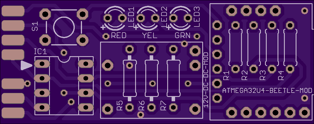
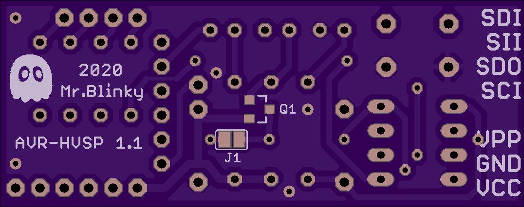
2 layer board of 2.15 x 0.85 inches (54.6 x 21.6 mm)
Uploaded:
April 11, 2020
Shared:
April 12, 2020
Total Price:
$9.15
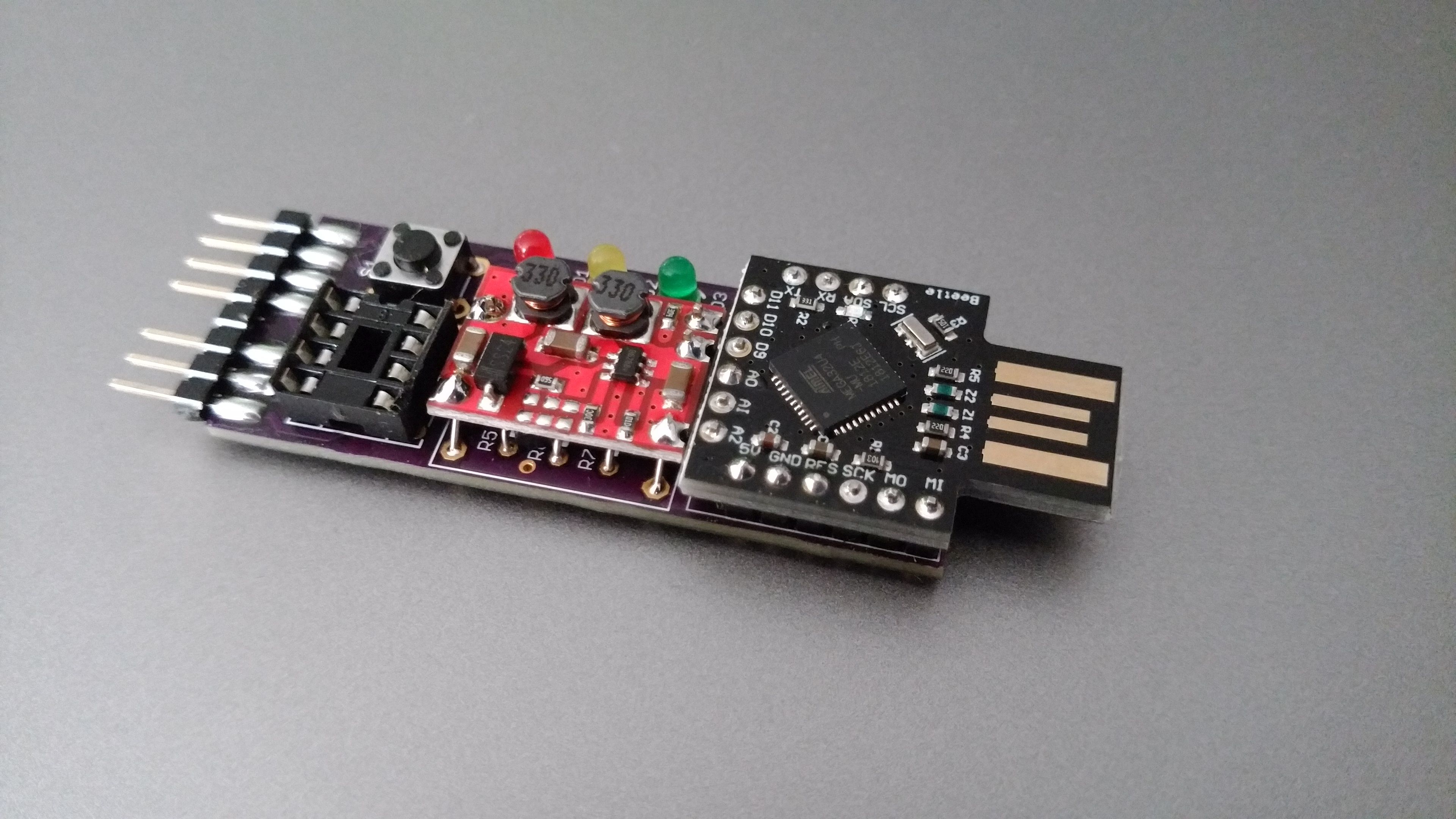
High voltage serial programmer for AVR Attiny devices
- Easy to make programmer using 12V DC-DC converter with enable and ATMEGA32U4 Beetle board.
- Programs AVR Attiny devices in high voltage mode to recover fuse settings and allows reset pin to be used as GPIO pin.
- Works with Arduino IDE / AVRdude
- No hassle with Windows driver utilities. Uses built in windows 10 driver or Arduino IDE driver.
GITHUB
https://github.com/MrBlinky/avr-hvsp
Parts
| Qty. | Discription |
|---|---|
| 1 | 12V DC-DC converter/booster module with enable |
| 1 | ATMEGA32U4 Beetle board without parts on PCB bottom + headers (No 3.3V pin and no extra GND pins on top row.) |
| 1 | 3 mm Red LED |
| 1 | 3 mm Yellow LED |
| 1 | 3 mm Green LED |
| 5 | 470 Ohm resistor (1/8 Watt) |
| 2 | 1K resistor (1/8 Watt) |
| 1 | PM48XP P-channel MOSFET SOT23 package (optional)* |
| 1 | 8 pin header (for programming connector) |
| 1 | 2 pin header (for DC-DC converter) |
| 3 | 1 pin header (for DC-DC converter) |
| 1 | 8 pin IC socket |
| 1 | 6x6mm tactile button |
*A MOSFET is recommended for a more powerful VCC. However if devices are only programmed using the IC socket or in low power circuits (<20mA), the MOSFET can be left out. In that case VCC is powered by a GPIO pin by shorting jumper J1. When using a MOSFET, Jumper J1 must be left open.
