I2C Counter
author: wymand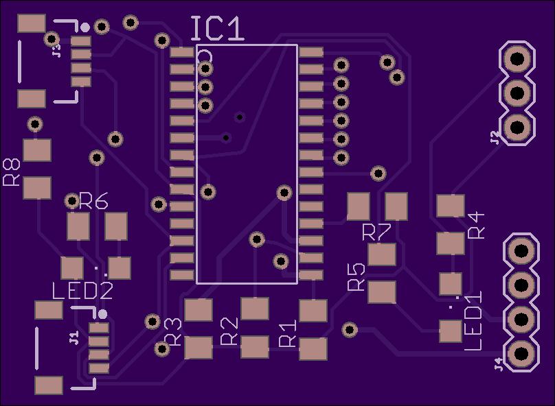
2 layer board of 1.62 x 1.18 inches (41.0 x 30.0 mm)
Uploaded:
February 01, 2018
Shared:
February 01, 2018
Total Price:
$9.50
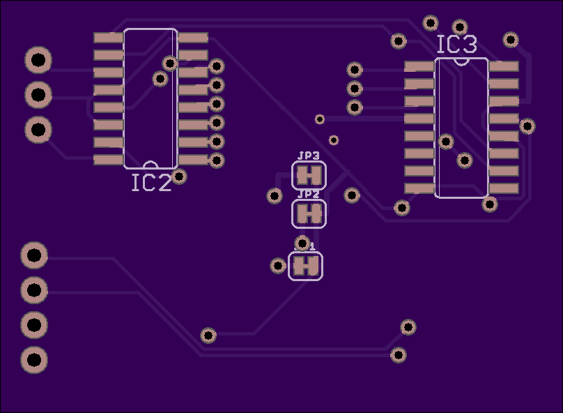
http://hiddenridge.net/wp/index.php/2018/02/01/i2c-12-bit-binary-counter/ This is version 4 of the board. The board uses 2 each 74LS590 binary counter chips in series. The chips are wired to give a 12 bit count buffered into an MCP23017 I2C GPIO chip. I added address cut traces for the I2C address. It now has two QWIIC connectors as well as a .1-in 4 pin opening for the I2C. The board counts on the low to high transition of the input. It has a power LED and a count LED. The count LED is enabled by a GPIO pin. The GPIO also has a clear function to zero the counters and a GPIO pin for latching the count into the output buffer of the 74LS590 for accurate read by the GPIO. The MCP23017 has two 8 bit GPIO registers The first 12 are dedicated inputs for the binary count. The last three are dedicated outputs for count clear, count buffer latch and to enable the count LED. The final GPIO has a tie point and can be used for a 13th bit to up the total count from 4095 max count to 8191, or it cam be used as a GPIO output.
http://hiddenridge.net/wp/index.php/2018/02/01/i2c-12-bit-binary-counter/ This is version 4 of the board. The board uses 2 each 74LS590 binary counter chips in series. The chips are wired to give a 12 bit count buffered into an MCP23017 I2C GPIO chip. I added address cut traces for the I2C address. It now has two QWIIC connectors as well as a .1-in 4 pin opening for the I2C. The board counts on the low to high transition of the input. It has a power LED and a count LED. The count LED is enabled by a GPIO pin. The GPIO also has a clear function to zero the counters and a GPIO pin for latching the count into the output buffer of the 74LS590 for accurate read by the GPIO. The MCP23017 has two 8 bit GPIO registers The first 12 are dedicated inputs for the binary count. The last three are dedicated outputs for count clear, count buffer latch and to enable the count LED. The final GPIO has a tie point and can be used for a 13th bit to up the total count from 4095 max count to 8191, or it cam be used as a GPIO output.
