Power Supply: AC Mains to Low Voltage DC
author: Eric
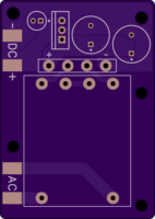
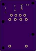
2 layer board of 1.63 x 2.30 inches (41.4 x 58.3 mm)
Uploaded:
January 15, 2014
Shared:
February 10, 2014
Total Price:
$18.70
Cost: $18.70 for three.
Description:
I needed a low voltage, low current DC power supply for a mains-powered project but I was out of spare wall warts, so I whipped this together and it does the job nicely.
Holes along the edges of the board are sized for M3 x 4mm standoffs and M3 or #4-40 hardware.
The transformer footprint will accept the Triad Magnetics F16-070-C2-B (max 70mA) or F16-150-C2-B (max 150mA). I used the latter. The transformer’s secondary windings are wired in series.
The bridge rectifier footprint will accept any 4-SIP package with 0.2-inch pin spacing and max 0.050-inch pin diameter. I used a GBU-package device that I had on hand.
The TO-220 footprint will accept any of the 78XX series of fixed output linear regulators. I have tested with the ON Semiconductor NCP7812TG and measured ~40mV peak-to-peak output ripple with 100mA load. The regulator settles at ~48°C under this load with no heatsink.
The large electrolytic capacitors are 10mm diameter with 5mm pin spacing. I used two Kemet ESK108M025AH4AA 1000uF 25V caps. The small electrolytic is 5mm diameter with 2mm pin spacing. I used a Kemet ESK107M016AC3AA 100uF 16V cap.
To simplify and save cost, the board has exposed copper pads for AC input and DC output connections instead of screw terminals. Apply a little flux and wires will solder on with ease.
CAUTION: This is a mains-powered circuit. Use appropriate care with exposed high voltage and please install a properly rated fuse inline with the hot AC supply line.

