Jasper Noise clock mod
author: mangros
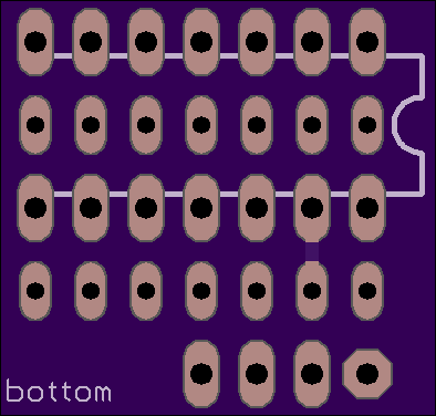
2 layer board of 0.79 x 0.75 inches (20.0 x 19.0 mm)
Uploaded:
July 23, 2017
Shared:
August 05, 2017
Total Price:
$2.95
The Jasper’s digital noise circuit is clocked by the keyboard scanner clock. This is fast enough to produce a natural sounding white noise.
This PCB will fit in the IC34 (the CD4006) socket and allow an alternate clock signal to be connected to the digital noise. A suitable source would be Oscillator 2’s square wave output after R99. This will create a raspy 80s computer explosion texture for the noise that will scale along the keyboard. (The Jasper LFO doesn’t go fast enough to achieve the main effect here.)
Fitting an SPDT switch will allow selection between the original noise clock and the alternate clock signal.

Use double-sided turned pin headers to mount this board to the main Jasper PCB.

If keeping a socket on the Jasper PCB and using a socket for the 4006 on this PCB, space under the panel is very tight. The official BOM suggests 17mm spacers and depending on your IC sockets, the board may not fit underneath the panel.
I used 18mm spacers so everything fits tightly but remains removable.
The Jasper’s digital noise circuit is clocked by the keyboard scanner clock. This is fast enough to produce a natural sounding white noise.
This PCB will fit in the IC34 (the CD4006) socket and allow an alternate clock signal to be connected to the digital noise. A suitable source would be Oscillator 2’s square wave output after R99. This will create a raspy 80s computer explosion texture for the noise that will scale along the keyboard. (The Jasper LFO doesn’t go fast enough to achieve the main effect here.)
Fitting an SPDT switch will allow selection between the original noise clock and the alternate clock signal.
Use double-sided turned pin headers to mount this board to the main Jasper PCB.
If keeping a socket on the Jasper PCB and using a socket for the 4006 on this PCB, space under the panel is very tight. The official BOM suggests 17mm spacers and depending on your IC sockets, the board may not fit underneath the panel.
I used 18mm spacers so everything fits tightly but remains removable.
