Elevator Trim Left Stick Priority (Rev F-TH)
author: Eric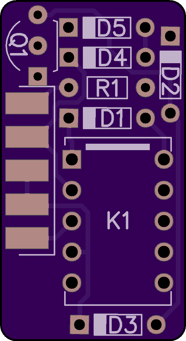
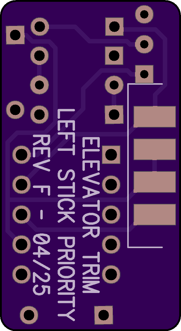
2 layer board of 0.60 x 1.10 inches (15.2 x 27.9 mm)
Uploaded:
April 16, 2025
Shared:
April 16, 2025
Total Price:
$3.30
This is a simple board to give left stick priority for elevator trim activation in Experimental category light aircraft.
This PCB fits between the solder cups of D-sub connector J1 and is soldered to the connector’s cups. The assembled module fits inside the connector backshell listed in the bill of materials.
All trim switches must pull this board’s inputs to ground. Both outputs from this board pull to ground. Do not connect the outputs directly to a trim motor; the module is intended to provide “up” and “down” signals to an elevator trim controller such as a TCW Technologies Safety-Trim unit or a relay deck.
Connect +12V, trim switches and trim controller to this module using a female 9-pin D-Sub receptacle and appropriate sockets. If a center trim switch is not installed, do not populate pins 3 and 7 of the mating receptacle (the center trim switch is provisioned to accommodate aircraft like the Kitfox, which is designed to have a single trim rocker switch on the center console; adding stick switches results in three sets of switch contacts).
This project is intended for use in Experimental category aircraft only. Do NOT install it in a CAR Part 3 or FAR Part 23 certificated aircraft without FAA Field Approval.
SCHEMATIC & WIRING DIAGRAM: Download here.
BILL OF MATERIALS (Digi-Key): https://www.digikey.com/en/mylists/list/MWE6AGTBZJ
