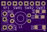
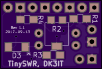
TinySWR (Deprecated)
author: mfhepp
2 layer board of 0.83 x 0.57 inches (21.0 x 14.4 mm)
Uploaded:
September 13, 2017
Shared:
September 13, 2017
Total Price:
$2.30
A simple SWR and RF indicator for QRP transceivers
Important: This PCB is superseded by https://oshpark.com/projects/JtKPis3T because it contained a bug. Do not use this PCB for new projects.
Assembly instructions and source files are on GitHub.
Warning: This OUTDATED version has at least one bug: The GND signal between the actual circuit and the antenna / rig connectors is not connected (because that missing link was hidden behind a junction in the schematic, so the ERC/DRC did not spot this).
I think that adding a short wire from the ANT GND (the rectangular pads) to any of the other pins that should carry GND (e.g. GND side of R3, R4, R5; cathode pins of SWR3 or RF1, or anode of D3) should do the trick, but this has not yet been tested.

