Crystal Oscillator Clock Driver
author: qwertymodo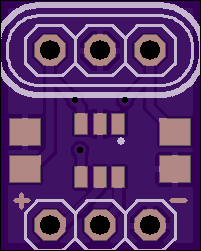
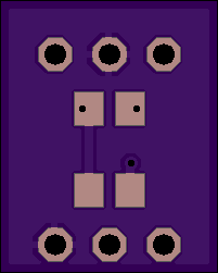
2 layer board of 0.40 x 0.50 inches (10.2 x 12.7 mm)
Uploaded:
July 28, 2013
Shared:
September 11, 2013
Total Price:
$1.00
Simple crystal oscillator clock generator. Requires only external connections for Vcc, Gnd, and the clock output.
Component list

OSC: HC-49 crystal/resonator[1]
IC1: TI SN74LVC1GX04DBVR (SOT-23)
C1/C2: 0805 SMD capacitors (omit if using a resonator w/internal capacitors)[2]
RS: 0805 SMD resistor[3]
RF: 0805 SMD resistor (1M-10M)
[1] Any standard HC-49 crystal or resonator should fit. The hole pitch is 2.54mm, but slight differences shouldn’t matter. Alternatively, the Samtec SL-103-G-39 socket strip can be used to swap out crystals at will.
[2] Crystal load capacitor values calculated from the crystal’s rated load capacitance, they are NOT the same as the load capacitance. Simplifying the calculation from the datasheet gives:
C1 = C2 = 2(CL + CS)
where CL is the crystal’s rated load capacitance and CS is the IC’s stray capacitance (5pF for the SN74LVC1GX04DBVR).
e.g. for a crystal rated for 18pF load capacitance, C1 = C2 = 26pF
[3] RS should be calculated to be roughly equal to the reactance of C2 at the target frequency
Simple crystal oscillator clock generator. Requires only external connections for Vcc, Gnd, and the clock output.
Component list
OSC: HC-49 crystal/resonator[1]
IC1: TI SN74LVC1GX04DBVR (SOT-23)
C1/C2: 0805 SMD capacitors (omit if using a resonator w/internal capacitors)[2]
RS: 0805 SMD resistor[3]
RF: 0805 SMD resistor (1M-10M)
[1] Any standard HC-49 crystal or resonator should fit. The hole pitch is 2.54mm, but slight differences shouldn’t matter. Alternatively, the Samtec SL-103-G-39 socket strip can be used to swap out crystals at will.
[2] Crystal load capacitor values calculated from the crystal’s rated load capacitance, they are NOT the same as the load capacitance. Simplifying the calculation from the datasheet gives:
C1 = C2 = 2(CL + CS)
where CL is the crystal’s rated load capacitance and CS is the IC’s stray capacitance (5pF for the SN74LVC1GX04DBVR).
e.g. for a crystal rated for 18pF load capacitance, C1 = C2 = 26pF
[3] RS should be calculated to be roughly equal to the reactance of C2 at the target frequency
