PCW Twin Gotek adapter board
author: JonB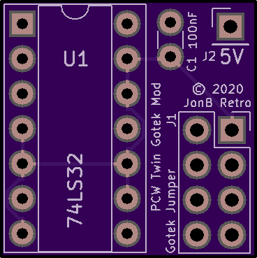

2 layer board of 0.74 x 0.74 inches (18.7 x 18.8 mm)
Uploaded:
January 30, 2021
Shared:
January 30, 2021
Total Price:
$2.70
Plug this board into the GoTek option jumper of Drive A: in a 2 Gotek - equipped PCW 9512, and jumper S1 in Drive B:; this will allow the PCW to boot with both drives, per Fabrizio Di Vittorio’s blog:
https://fabriziodivittorio.blogspot.com/2018/05/installazione-gotek-su-amstrad-pcw-9512.html
The orientation of the board on the Gotek PCB as follows:
- the 8 way female jumper header is soldered to the UNDERSIDE of the board
- with the Gotek 34 way header on the right, mount the board so that the female pin connector is at the top of the longer (14 pin) jumper block.
- the LS32 is to the LEFT of the jumper block and the 5v pin is top right
- use a jumper to connect +5v to the right hand pin of J4 (closest to the power input socket).
WARNING - When connecting the Gotek to the PCW power socket, be aware that on a PCW 12v and 5v lines are swapped. Check with a multimeter BEFORE plugging the PCWV connector into your Gotek, you will probably need to swap the wires around.
Solution designed and prototyped by Fabrizio Di Vittorio. Schema capture and board layout by JonB.
