MSP430G2553 sensor board
author: flabbergast
2 layer board of 1.93 x 1.14 inches (48.9 x 28.8 mm)
Uploaded:
June 20, 2019
Shared:
July 17, 2019
Total Price:
$10.90
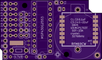
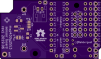
A board designed for MSP430G2553 (DIP-20), RFM69CW radio, and a power source (battery or otherwise). Fits Hammond 1551HBK box. Just add a sensor and some (forth) code! Longer info here.
Notes:
Any other pin compatible MSP430 would work as well, but to run Mecrisp Forth, 16kB flash is needed. (The radio chip select line is connected to P2.0, so to use it on 14 pin chips, connect to one of the available P1.x with a wire.)
There is a footprint for a cylindrical 32768Hz crystal; this is needed for low power modes.
There is a little prototyping area; all unused MCU pins are routed out.
Hammond 1551HBK is a black box, dimensions 60x35x20mm. They also have a gray and translucent blue versions, called 1551HGY and 1551HBU.
The intention is to use the CR2032 holder footprint to mount the holder over the radio, and use the battery to directly power the MCU and the radio. But, there is also an option to solder in a MCP1703T voltage regulator (plus 2 stabilising capacitors, 0805), and connect a power source to one of the ``VIN pads. For this, one can mount a JST connector on the bottom side (works with LiPo batteries).
Once the voltage regulator is mounted, it is possible to connect/disconnect it to the rest of the circuit with the solder jumpers. It is also possible to connect VIN with VDD directly.
The TX/RX, RESET, TEST pins, together with GND and `VIN pins, are routed to an UART/FTDI 6 pin connector on the side of the board. With the ‘usual’ arduino-style USB-to-UART converters, RESET should match the DTR signal, and TEST the CTS/RTS. (Note that you’ll need 3.3V-level signals!)

